Hello, steemians, and welcome to my workshop, eh!
This is part 2 of my series on building this little amplifier that I've decided to call the "Red and Black" amp, at least for now. I'm doing these posts as I progress with the build, so I'm not sure when the next part of the series will get posted.
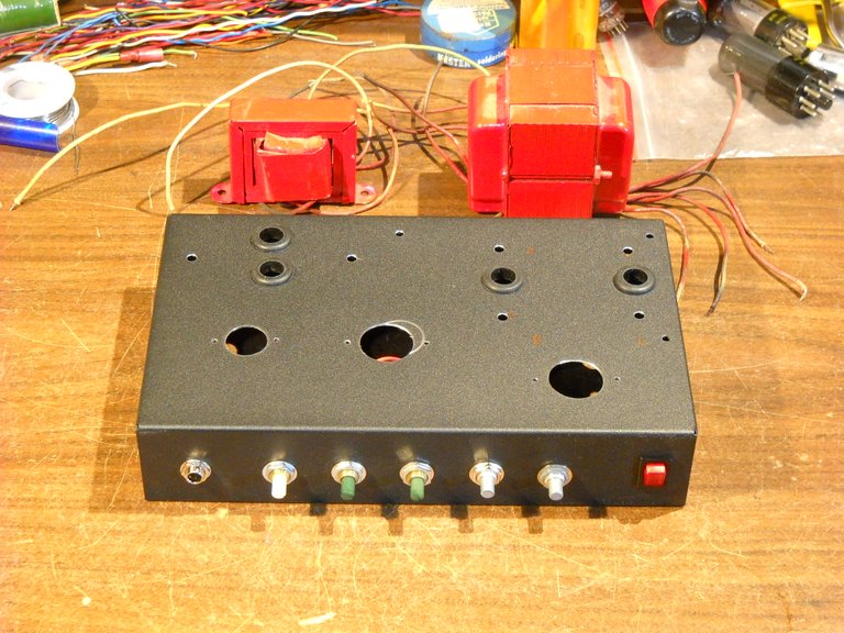
My first post about building this little guitar amp explained how I set up the chassis for this amp by laying out and drilling all the mounting holes for the various parts that mount to the chassis. At the point where my last post ended, I was ready to mount the transformers and tube sockets, but I still needed to drill 3 holes in the back of the chassis for parts.
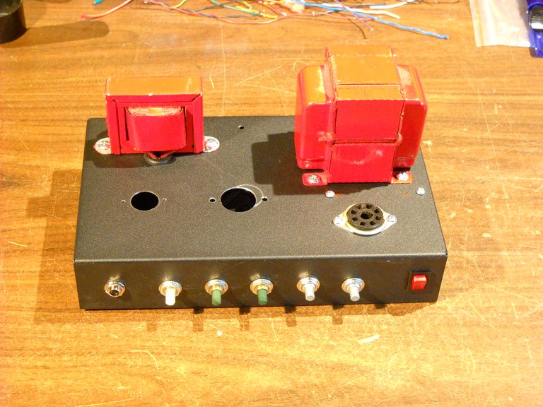
After drilling the 3 holes in the back of the chassis, I started the process of mounting the parts. The first thing I did was to mount both transformers and the rectifier tube socket.
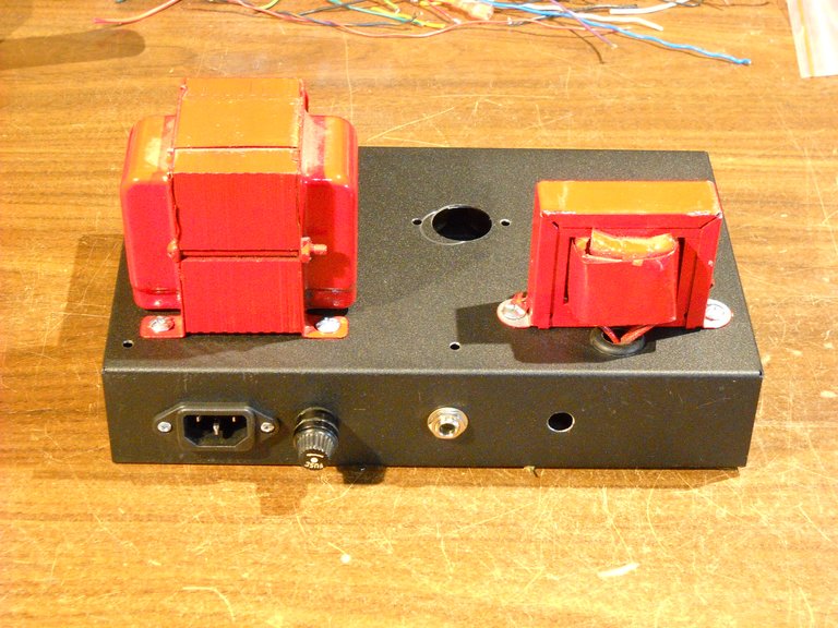
After that, I mounted the fuse holder and the speaker output jack on the back of the chassis. I still need to get the speaker impedance switch to put in the remaining hole.
After I had all of those parts mounted, I started building the circuitry on the inside of the chassis. I started by building the power supply circuits. The 2 black tubes with the printing on them are the primary power supply capacitors. I also have the AC plug, the fuse holder, and the power switch wired in, as well as the rectifier tube socket. You can't see the bottom of the socket very well here because there are parts covering up half of it.
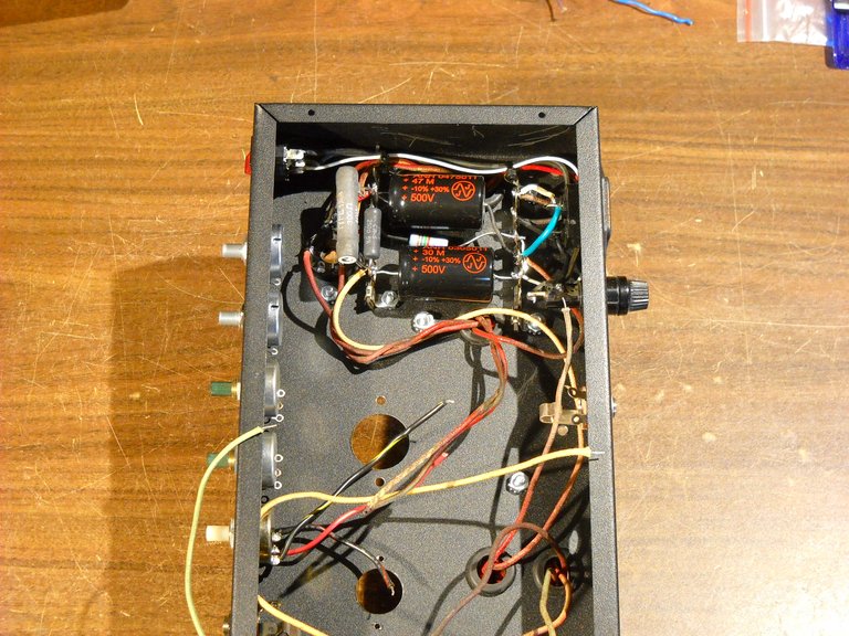
Right now, it looks like a tangle of wires inside the amp, but half of them are for the audio circuits so they're not hooked up to anything yet. My next step with building this amp will be to install the other two tube sockets and then start on the audio circuits. It will probably be the end of next week before that happens.
Stay tuned for the next part of this series!
You can read the first post about this amp here.
https://steemit.com/guitaramp-build/@amberyooper/a-new-guitar-amp-build-part-1
That's all I have for this post, I hope you found it interesting!

Thanks for stopping by my page and checking out my post, eh!
As always, feel free to leave a comment or a question if you would like.
May the Steem Force be with you!


It's so cool seeing an amp stripped down to this level of simplicity, at least cosmetically speaking I mean. Just the guts lol. Very impressive that you can navigate this kind of project.
Thank you!
These amps look more complex than they actually are. It's when you get into solid state amps that things get complex. You can't modify a transistor amp the way you can a tube amp because of the way transistors work.
Yeah it definitely seems complex to an uneducated eye haha. But that's cool!
I had a buddy who was really into modding guitar pedals at one point. I always thought the electronic side of all that amp modelling and effects stuff was super interesting. Must be kind of liberating to have the ability to literally make your own sound haha.
It's definitely an interesting hobby for me. I try to save money on these build by using vintage transformers from older sound equipment. The transformers are easily the most expensive part of building one of these amps.
Yeah I can imagine it'd get pricey. Well looking forward to following your progress and seeing where you end up on that!
Looking good. Is there any specific amp this circuit design is based on?
Thanks!
The amp is loosely based on the Fender Champ, but it has more power. I'm using the tone control circuitry of the "blackface" Fender amps, that seems to be about the best configuration in a Fender.
The Marshalls are set up different and have less bottom end, in general.
It's good to see you again, it's been a little while!
When making an AC device that will have a computer plug and a fuse, i like to use an all in one piece. Thus, i only have to cut one hole. And often, I get a AC-in, fuse and switch all in one.
The fuse holder you put in is much easier to change... but that really depends on how often fuse changes will take place. I tend to work with digital circuits, which is 5Volts-ish, so not much will blow the fuse accept outright circuit failure or something really shtupid.
So, why your choice of components?
The choice of the fuse holder is mostly because that's what you typically see on most tube type guitar amps. I guess it's what I'm familiar with. I've see those all in one power jacks with the fuse and switch, but that kind of seems too modern for a tube amp. :-)
The main reason that I use a removable power cord is because figuring out what to do with an attached cord is a pain when you're not using the amp.
The attachment of a power cord is SUCH A PAIN, that even designing things for large scale manufacturing, it is cheaper to use a removable power cord.
Now, they are so ubiquitous that getting a computer cord is cheaper than getting one with tinned pigtails.
Save money AND make manufacturing easier.
Yep, that's how I see it also. :-)
I love stuff like this...
Thanks!
It's all done and you flip the
switch. like Frankenstein
I bet it's fun when
It's all done and you flip the
Switch. like Frankenstein
- vladivostok
I'm a bot. I detect haiku.
thank you...let me restructure this for you buddy
That haikubot! LOL
I built an amp like this one a couple of years ago and it's a lot of fun to mess around with. It's not super loud but can get some interesting tone out of it.
I'm waiting to see how well this one turns out. :-)
can't wait to hear my friend, I have very little patience for such project, usually when i do them its with a friend that has experience and patience,,,,,,,haiku that shit :)