Note
- This is my English translated paper of the original Indonesian paper published at National Conference on Smart-Green Technology in Electrical and Information Systems (CSGTEIS), Bali, 14-15 November 2013.
- The copyright has been transferred to the Department of Electrical Engineering, Faculty of Engineering, Udayana University, and based on the agreement, the author is allowed to upload this article to blogs and websites on the to provide the link to the copyright owner's publication website, namely https://ojs.unud.ac.id/index.php/prosidingcsgteis2013/article/view/7259. This means that all of these writings are not licensed under creative commons but copyrighted © under Department of Electrical Engineering, Faculty of Engineering, Udayana University where other people must ask for permission from us for reposting.
- Authors: Fajar Purnama, I Made Oka Widyantara, dan Nyoman Putra Sastra.
Abstract
Previously, wireless sensor network (WSN) Imote2 used the Intel Platform X, SOS, and TinyOS operating systems. Now Platform X and SOS are no longer being developed, so many researchers are using TinyOS. End users of TinyOS on the Imote2 platform encounter many limitations such as implementing complex routing. Therefore the Embedded Linux community develops embedded Linux for the Imote2 platform. This paper discusses in detail the steps to embed Linux on the target, namely the Imote2 platform WSN radio sensorboard device. Host is a Linux operating system. The developer includes 3 main components, namely the bootloader, Linux kernel, and filesystem. Embedding is done by flashing the JTAG interface using the OpenOCD software. After embedding, configuration is done on the target via serial connection. Configuration includes automatically enabling IP address, SSHD, and radio. Finally compared to the target performance using IEEE 802.11 WLAN and IEEE 802.15.4 ZigBee as transmission media. The result is that the use of IEEE 802.11 WLAN is more wasteful of memory and electricity.
Keywords: Wireless Sensor Network, Imote2, Embedded Linux, ZigBee, WLAN, JTAG, OpenOCD.
Introduction
Overall this paper consists of 4 parts. The first part of "Introduction" provides a brief overview of wireless sensor networks (WSN), some of the research that has been done in the field of WSN, and what will be discussed in this paper. The second part "Intel Mote 2 (Imote2)" describes WSN devices with the Imote2 platform. In this section you can see the physical form of the tool and mention some of the operating systems that are implemented on this platform. In the third part "Embedded Linux Implementation", the steps for installing the Linux operating system on the Imote2 platform are written. The last part is "Conclusion".
WSN or better known as a wireless sensor network (WSN) is a sensor device that communicates wirelessly to each other. These devices are placed over large geographic areas and form a network of sensors. This WSN does not have to be connected to the Internet. The main task of this sensor is to collect information from the surrounding environment, after which it sends the information to the user's device via the sensor network. This tool has been applied in the fields of civil, medical, and many other fields [1].
The existence of WSN is based on many limitations, such as limited power and limited wireless channel capabilities. Therefore, these wireless sensors form a network called WSN. Apart from being necessary to strategically place sensors (overcoming coverage holes), efforts are also needed to save energy and time in providing continuous information because the resources on WSN are limited [2]. An overview of the JSN can be seen in Figure 1.

Figure 1 WSN illustration [3]
In WSN there have been several previous studies such as research [4] which uses multiple WSN cameras to capture the same image. The device is placed in a different position but aimed at the same object. Combining images captured at different angles can improve image quality. At the end of the study, a form of WSN that works on this concept was proposed. The research [5] led to the modeling of low power consumption WSN cameras by determining image quality. This research concludes several points that need to be considered in the WSN camera modeling, namely (i) camera selection method (ii) image compression method and strategy (iii) image transmission method. But this paper will not discuss WSN in that scope.
Unlike [4] and [5] this research is about embedded Linux in WSN, as has been done by Researcher [6], [7], and [11]. At [6] and [7], the performance of the Imote2 platform on their respective wireless sensor networks uses IEEE 802.15.4 Zigbee and IEEE 802.11 WLAN networks. While the embedded linux implementation model on WSN, these two studies use the same scheme, namely (i) connecting a multimedia WSN device to a computer (ii) installing a bootloader, Linux kernel and filesystem (iii) managing the internet protocol (IP) network and the secure shell daemon (SSHD) (iv) activate radio (v) measure memory consumption and power consumption.
After this is done, we can add some features, such as capturing images with the IMB400 camera sensor board which is visible at [8] and [9]. However, this paper does not go that far, but discusses embedded Linux on the Imote2 platform radio sensorboard in detail.
Intel Mote 2 (Imote2)
Imote2 is a platform on the WSN device developed by Intel Research in the platform X research section. This device is built with low power consumption, with a PXA271 XScale CPU processor, and is integrated in IEEE 802.15.4 ZigBee [10]. This processor (Intel Xscale processor PXA271) can operate at low voltages (0.85V) and frequencies of 13MHz to 104MHz. The frequency can be increased up to 416MHz by setting the voltage [11]. In general, Imote2 consists of 4 parts as shown in Figure 2.
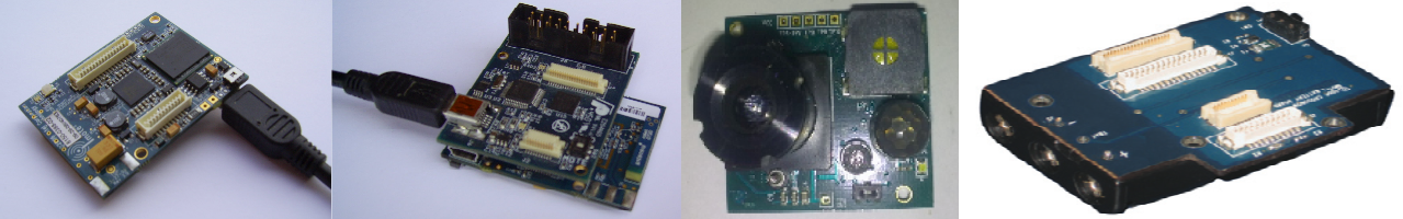
Figure 2 radio processor board (IPR2400) [11], interface board [11], sensor board (IMB400) [8], and power supply board (IBB2400) [12].
The PXA271 consists of 3 chips (i) the processor itself (ii) 32MB SDRAM (iii) 32MB flash. The radio used is the TI CC2420 which is based on IEEE 802.15.4 ZigBee, where devices with this standard at the PHY and MAC layers operate at low power and short-range radio, targeted for control and monitoring applications. The CC2420 also supports a 250kbps data rate with 16 channels on the 2.4GHz frequency [11].
Previously Imote2 worked on Intel Platform X. After Imote2 moved to Crossbow, Intel Platform X was no longer being developed because Crossbow released its own operating system. Operating systems mostly developed by communities such as SOS. However, SOS stopped being developed in 2008. Currently, what is still visible is TinyOS and Linux [11].
Prior to Embedded Linux, the operating system used on Imote2 was TinyOS. Most publications on the web use TinyOS such as [10], [13], and [14]. Embedded Linux is now being developed because it finds limitations on TinyOS such as complex-routing in a WSN topology. The Embedded Linux community sees the Imote2 Embedded Linux operating system as a solution to overcome these limitations. However Embedded Linux in Imote2 is still new and under development [8].
Embedded Linux Implementation
The device used is the same as the ones used in [6-9] and [13-15], the Imote2 platform multimedia sensorboard radio has (i) 256KB SRAM memory (ii) 32MB flash (iii) 32MB SDRAM (iv) integrated radio with 802.15.4 (v) optional radio from SDIO and UART (vi) 2.4GHz antenna (vii) basic and advanced connectors such as 3xUART , I2C, 2xSPI, SDIO, I2S, AC97 audio, USB host, I/F camera, mini USB GPIO. The architecture of the device can be seen in Figure 3.
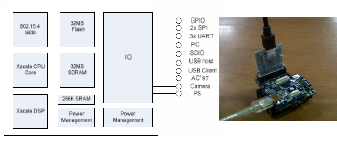
Figure 3 the Imote2 sensorboard architecture [4], and the Imote2 sensorboard [5]
This section will discuss in more detail the technical details of embedding Linux on the target, namely the Imote2 platform multimedia radio sensorboard with the main source [11]. Host is Linux OS. Linux distributions can be used anywhere, but the commands in this paper are based on Ubuntu or Debian. In brief, the stages can be seen in Fig. 4.
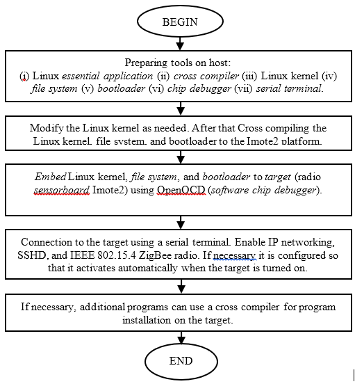
Figure 4 flowchart briefly about embedding Linux on Imote2
The [6] and [7] research mainly prepares a cross compiler and chip debugger. Commands are entered based on [13]. But not using TinyOS here. The cross compiler used is a compiled cross compiler, namely GCC and GLIBC from http://sourceforge.net/projects/imote2-linux/files/imote2-tools-linux. It is still better to compile your own cross compiler to better suit your device requirements.
If the compressed file is in the form of a gunzip tape archive it can be extracted with the following command:
tar xzvf /file-location/file-name.tar.gz
If it is in the form of a bunzip2 tape archive it can be extracted with the following command:
tar xjvf /file-location/file-name.tar.bz2
If the directory is not given full access, then the read, write, and execute conditions need to be given the binary number "1". If it gives full access then rwx (read write execute) is "111(2)" which is "7(10)". Then the command:
chmod –R 777 /lokasi-directory/namadirectory
The first "7" is to give rwx access to the administrator, the second to the user, and the third to the group, while the "-R" is to apply to all contents in that directory. The use of this cross compiler will be discussed at the same time when forming the Linux kernel. In this paper the steps are as follows (it is a directory with a downloaded cross compiler):
tar xzvf linux-gcc-4.1.2-arm-xscale-linux-gnu-glibc-2.3.3.tgz
chmod –R 777 arm-xscale-linux-gnu
Before starting we recommend downloading the necessary dependencies:
apt-get install libncurses5-dev libusb-dev libftdi1 libftdi-dev ldconfig mtd-tools ssh
Furthermore, the Linux kernel is used from http://www.kernel.org/pub/linux/kernel version 2.6.29.1 rc 1.1 or can be obtained from "git" which is available by the community. If necessary, extract and modify the Linux kernel permissions. After that, go to the directory and set up the cross compiler. Especially for Kernel compiling, in a file called "Makefile" there are lines "ARCH =" and "CROSS_COMPILE =" which need to be declared (still empty). To declare universally see the following command:
cd /Linux-kernel-directory-location
export ARCH=arm
export CROSS_COMPILE=/cross-compiler-directory-location/bin-location/cross-compiler-name
In this paper, the commands are as follows (Linux kernel and cross compiler in one directory):
tar xzvf linux-2.6.29.1.tar.gz
chmod –R 777 linux-2.6.29.1
cd linux-2.6.29.1
export ARCH=arm
export CROSS_COMPILE= ../arm-xscale-linux-gnu/bin/arm-xscale-linux-gnu-
With this command, the platform is determined to be "arm" (a platform for small devices) and use the cross compiler "arm-xscale-linux-gnu", the directory "arm-xscale-linux-gnu/bin" contains the file "arm-xscale-linux-gnu-gcc”, “arm-xscale-linux-gnu-g++”, and others. To manage what is compiled, see the “Makefile” file. To make it easier to use make menuconfig. Then it requires "libncurses5-dev". Then it is necessary to copy the file "imote2-linux_defconfig" to the /root directory to be the name ".config".
cp /Linux-kernel-directory-location/imote2-linux_defconfig-file-location/imote2-linux_defconfig /root/.config
In this paper the command (still in the Linux kernel directory):
cp arch/arm/configs/imote2-linux_defconfig /root/.config
To compile a kernel:
make menuconfig
Here you can set whatever you want to install.
make image-type
The image type is usually zImage or bzImage. In this paper:
make zImage
Next create the module:
make module
make INSTALL_MOD_PATH=$PWD/modules modules_install
This command will install the module in a directory named "modules".
When finished compiling Linux kernel is compile filesystem. The source of the filesystem used is from http://sourceforge.net/projects/imote2-linux/files/imote2-rootfs. You also need the mkfs.jffs2 tool found in mtd-tools. JFFS2 (Journaled Flash File System 2) is a file system designed to flash device files on embedded systems. After extracting the file system directory, the modules compiled in the Linux-kernel are copied into this directory.
To create a 16MB filesystem:
mkfs.jffs2 --squash-uid -r ./linux-rootfs -o rootfs.jffs2 -e 0x20000 --pad=0x01000000
To create a 32MB filesystem:
mkfs.jffs2 --squash-uid -r ./linux-rootfs -o rootfs.jffs2 -e 0x20000 --pad=0x01DC0000
The last material needed after the Linux kernel and filesystem is the bootloader. In this paper, the bootloader used is available at http://sourceforge.net/projects/imote2-linux/files/blob-im2.
When the material is available, the next process is to embed it on the Imote2 platform radio sensorboard. As in the research [6] and [7] steps for flashing, in this paper the flashing steps are based on the tutorial [14] provided that they do not follow any of the steps using TinyOS. For flashing it is necessary to install the FTDI JTAG interface driver. The packages required on the host are libusb-dev, libftdi1, libftdi-dev, and ldconfig. The OpenOCD used is available at http://downloads.sourceforge.net/project/openocd. The steps for installing OpenOCD are as follows (in the extracted OpenOCD directory):
./configure --enable-ft2232_libftdi
make
make install
chmod –R 777 /installed-openocd-locations
openocd -f /configuration-file-location -f /configurationintelmote-file-location
In this paper the steps are as follows:
tar xjvf openocd-0.4.0-rc1.tar.bz2
cd openocd-0.4.0-rc1
./configure --enable-ft2232_libftdi
make
make install
chmod –R 777 /usr/local/bin/openocd
Connect the USB cable as shown 4.(b). Command to connect target to host:
openocd -f /location/file/configuration –f /location/file/configuration-intelmote
In this paper, embed the bootloader, Linux kernel, and filesystem as follow (in the directory containing the bootloader file, Linux kernel directory, and filesystem directory):
openocd –f /usr/local/share/openocd/scripts/interface/ jtagkey.cfg –f board/crossbow_tech_IMote2.cfg
telnet localhost 4444
reset halt
flash protect 0 0 258 off
flash erase_sector 0 0 258
flash write_image blob-im2 0x0 bin
flash write_image linux-2.6.29.1/arch/arm/boot/zImage /zImage
0x00040000 bin
flash write_image rootfs.jffs2 0x00240000 bin
Command "reset halt" is so that the target is halted, command "flash protect 0 0 258 off" is to remove protect, command "flash erase_sector 0 0 258" is to erase the contents of the sector (delete contents), and command "flash write source destination" is to fill the target from the host.
If all the steps have been implemented then Linux has been successfully embeded. Lastly is the configuration on the target via serial connection, such as [6], [7], and [15]. Before continuing, connect the USB cable as Figure 5.
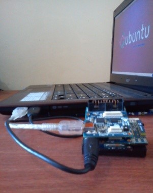
Figure 5 How to connect the USB cable
The serial terminal application on the host can be used with PuTTY, GTKterm, and many other applications. For serial connection from host to target, the following settings are required:
- Connection type : serial
- /dev/ttyUSB1 (atau 0)
- Speed 115200
- Data bit: 8
- Stop bit: 1
- Parity: none
- Flow control: XON/OFF
The IP address used is 192.168.99.101/24. To enable IP address and SSHD automatically, and change IP address, the steps are as follows:
ln -s /etc/init.d/networking /etc/rc2.d/S10networking
ln -s /etc/init.d/sshd /etc/rc2.d/S11sshd
ln -s /etc/init.d/networking /etc/rc5.d/S10networking
ln -s /etc/init.d/sshd /etc/rc5.d/S11sshd
vi /etc/init.d/networking (ganti IP address)
vi /etc/network/interfaces (ganti IP address)
Next, make a script so that the radio starts automatically. The script is stored in the "/root/tosmac" directory with the name loaddriver, and the contents of the loaddriver are as follows:
#!/bin/sh
insmod /lib/modules/2.6.29.1_r1.1/kernel/arch/arm/mach-pxa/ssp.ko
insmod /lib/modules/2.6.29.1_r1.1/kernel/drivers/tosmac/tos_mac.lo
mknod /dev/tosmac c 240 0
So to activate the radio and be able to send data automatically the steps are as follows:
ln –s /root/tosmac/loaddriver /etc/rc2.d/S12loaddriver
ln –s /root/tosmac/loaddriver /etc/rc5.d/S12loaddriver
ln –s /root/tosmac/CntToLeds /etc/rc2.d/S14Transmitter (automatic data sender)
ln –s /root/tosmac/CntToLeds /etc/rc5.d/S14Transmitter (automatic data sender)
The embed and configuration stage is complete.
In contrast to the research [6] which uses IEEE 802.15.4 ZigBee radio transmission, research [7] uses IEEE 802.11 WLAN radio transmissions. At [7] a daughter board is created which will be connected to the TP-LINK USB WLAN as shown in Figure 6.
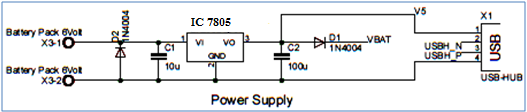
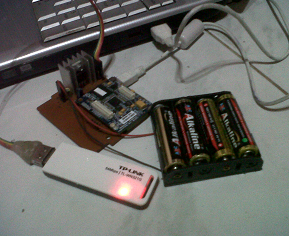
Figure 6 Daughter board [7] (a) schema (b) tools
First, you need to activate USB host support by adding the following script in the linux-2.6.29.1/arch/arm/mach-pxa/imote2.c file. The script is as follows [7]:
//baris pertama
#include <mach/ohci.h>
//isi

/*
* Configure USB Host (OHCI)
* For Imote2 the following configuration is used:
* USB Port 1 is used as USB Host
* USB Port 2 is used as USB Gadget (as default for Imote2)
*/

static int imote2_ohci_init(struct device *dev) {
return 0;
}

static struct pxaohci_platform_data imote2_ohci_platform_data = {
.port_mode = PMM_NPS_MODE,
.init = imote2_ohci_init,
.flags = ENABLE_PORT1 | NO_OC_PROTECTION,
.port_mode = PMM_PERPORT_MODE,
.power_budget = 150, //300
};
//baris terakhir

pxa_set_ohci_info(&imote2_ohci_platform_data);
In "make menuconfig" it is configured as follows [7]:
1\. Configure the USB-Host module.
Device Drivers >USB support >Support for Host-side USB <*>
  >USB device filesystem [*]
  >USB device class-device (DEPRECATED)[*]
  >USB Monitor<*>
  >OHCI HCD support<*>

2\. Configure the 802.11 Wireless LAN module.
Networking support >wireless >Improved wireless configuration API (M)
  >nl80211 new netlink interface support [*]
  >Wireless extensions sysfs files [*]
  >Common routines for IEEE802.11 drivers (M)
  >Generic IEEE 802.11 Networking (M)
  >Enable LED triggers [*]
  Device Drivers >Network device Support >Wireless LAN
    >Wireless LAN (IEEE 802.11) [*]

3\. TP-Link WN-321G (rt73) driver module configuration.
Device Drivers >Network Device Support>Wireless LAN
  >Ralink driver support [M]
  >Ralink rt2501/rt73 (usb0 support) [M]
  >Ralink debug output [*]
Then repeat the steps from compiling the Linux kernel and filesystem to flashing and configuration. In the research [7] using TL-WN321G (TP-LINK), the Linux driver version can be downloaded on the official site. The installation steps are as follows:
tar xvf TpLink_TL_WN321G_in_Linux.tar
cd TpLink_TL_WN321G_in_Linux/Module/
gedit Makefile
- Add lines “PLATFORM=EMBEDDED”.
- Omitting lines “PLATFORM=PC” and “PLATFORM=CMPC”.
- Manages links from compiled kernel sources.
ifeq ($(PLATFORM),EMBEDDED)
LINUX_SRC=../linux-2.6.29.1
endif

#export ARCH=arm
#export CROSS_COMPILE=../arm-xscale-linux-gnu/bin/arm-xscale-linux-gnu-
#make all
The compilation process will produce a file called "rt73.ko" which will be used as a module for the Wireless Lan 802.11 driver. Then copy the data to the target with the following command:
scp rt73.ko root@192.168.99.101:/root rt73.ko
Furthermore, the target script is created so that the radio is activated automatically based on the steps from [7].
ssh –l root 192.168.99.101
vi /etc/rc2.d/S50StartupScript
The script is like this:
#*********************************************************
#********S50StartupScipt File*****************************
#********This file configures Wlan on Imote2**************

#install driver
cd /root/
insmod rt73.ko
echo -n 1 > /sys/bus/usb/devices/1-1/bConfigurationValue

#Configure Wlan
sleep 10
ifconfig rausb0 up
iwconfig rausb0 essid imote2
iwconfig rausb0 mode ad-hoc
ip link set rausb0 up
ifconfig rausb0 inet 192.168.1.2
ifconfig rausb0 netmask 255.255.255.0
ifconfig rausb0 gateway 192.168.1.1
#********EOF S50StartupScript File*************************
chmod 777 S50StartupScript
The configuration stage when using IEEE 802.11 WLAN has been completed. When compared to the two studies, [7] is more wasteful on both memory consumption and electricity consumption than [6]. In the study [7] the memory consumed was 16.9MB from 29.8MB, while at [6] only consumed 13.6MB from 29.8MB. Electric power consumption can be seen in Figure 7.
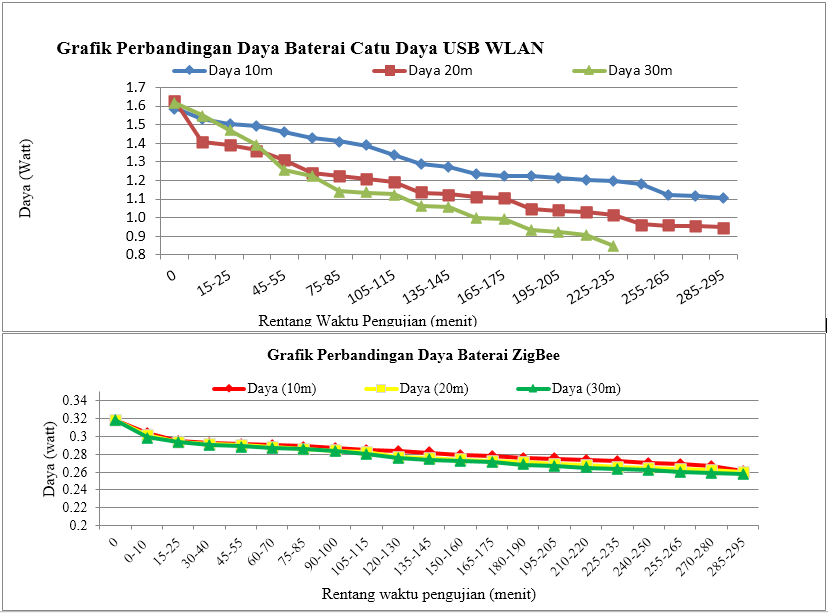
Figure 7 The power consumption of the target device [6], and devices [7]
Conclusion
From this paper, the following conclusions can be drawn:
- The Linux kernel is cross-compiled to the Imote2 platform first. The next process builds the filesystem and prepares the bootloader.
- To embed the bootloader, Linux kernel, and filesystem on the target via the JTAG interface using OpenOCD software, the process is called flashing.
- Target configuration includes automatic activation of IP addresses, SSHDs, and radios via serial connection, by linking to configuration scripts in RC level 2 and level 5.
- From research [6] and [7] use transmission media with the IEEE 802.11 WLAN standard on the Imote2 platform it is more wasteful of memory and power than using transmission media with the IEEE 802.15.4 ZigBee standard.
Reference
- H. Y. Shwe, C. Wang, P. H. J. Chong, A. Kumar. "Robust Cubic-Based 3-D Localization for Wireless Sensor Networks," wireless sensor network, vol. 5, no. 9, hal. 169-179, September 2013. [online]. Tersedia: www.scirp.org. [access on: 12 Oktober 2013]
- http://upload.wikimedia.org/wikipedia/commons/thumb/2/21/WSN.svg/537px-WSN.svg.png. [access on: 14 Oktober 2013]
- N. P. Sastra. “Wireless Sensor Network,” 18 Desember 2009. [Entri Blog]. Blog Wireless Sensor Network Nyoman Putra Sastra. Tersedia: http://staff.unud.ac.id/~putra/2009/12/18/wireless-sensor-network.html. [access on: 14 Oktober 2013].
- N. P. Sastra, Wirawan, G. Hendrantoro, “Virtual View Image over Wireless Visual Sensor Network,” Telkomnika, vol.9, no.3, hal. 489-496, Desember 2013. [online]. Tersedia: http://journal.uad.ac.id/index.php/TELKOMNIKA/article/view/1286/677. [access on: 14 Oktober 2013].
- N. P. Sastra, D. M. Wiharta, I. M. O. Widyantara, Wirawan. “Modeling Wireless Visual Sensor Network with a Low Energy Consumption for Desired Image Quality and View Point,” academia.edu shared research [online]. Tersedia: http://www.academia.edu/831948/Modeling_Wireless_Visual_Sensor_Network_with_a_Low_Energy_Consumption_for_Desired_Image_Quality_and_View_Point. [access on: 14 Oktober 2013].
- I. M. Wiasta, "Performasi Platform Imote2 pada Jaringan Sensor Nirkabel," Laporan Tugas Akhir, Jurusan Teknik Elektro., Universitas Udayana, 2012.
- F. S. Natha, "Performasi Platform Imote2 Menggunakan Standar 802.11 pada Jaringan Sensor Nirkabel," Laporan Tugas Akhir, Jurusan Teknik Elektro., Universitas Udayana, 2012.
- N. P. Sastra, Wirawan, G. Hendrantoro, “Design and Implementation of Wireless Multimedia Sensor Network Nodes Based on Linux OS,” academia.edu shared research [online]. Tersedia: http://www.academia.edu/454554/Design_and_Implementation_of_Wireless_Multimedia_Sensor_Network_Nodes_Based_on_Linux_OS. [access on: 14 Oktober 2013].
- N. P. Sastra. “Test Capture Image pada Intelmote 2 aka My First IMB400 Image,” 18 April 2010. [Entri Blog]. Blog Wireless Sensor Network Nyoman Putra Sastra. Tersedia: http://staff.unud.ac.id/~putra/2010/04/18/test-capture-image-pada-intelmote-2-aka-my-first-imb400-image.html. [access on: 18 September 2013].
- Stanford, “Imote2,” stanford.edu [online]. Tersedia: http://tinyos.stanford.edu/tinyos-wiki/index.php/Imote2 [Terakhir dimodifikasi: 15 Mei 2013, 14:07].
- Jorg Kasteleiner, “Principles of applying Embedded Linux on Imote2,” Diploma Thesis, Faculty of Computer Science and Engineering., University of Applied Sciences Frankfurt am Main, 2010.
- “WSN_Imote2_HW_Bundle_Datasheet,” Crossbow Technology Inc, San Jose, California.
- N. P. Sastra. “Langkah-Langkah Instalasi TinyOS 2.1.0 Intel mote 2 pada Ubuntu 8.04/9.04/9.10,” 18 Desember 2009. [Entri Blog]. Blog Wireless Sensor Network Nyoman Putra Sastra. Tersedia: http://staff.unud.ac.id/~putra/2009/12/18/langkah-langkah-instalasi-tinyos-untuk-intel-mote2.html. [access on: 18 September 2013].
- N. P. Sastra. “Flashing Program pada Intelmote2,” 17 April 2010. [Entri Blog]. Blog Wireless Sensor Network Nyoman Putra Sastra. Tersedia: http://staff.unud.ac.id/~putra/2010/04/17/flashing-program-pada-intelmote2.html. [access on: 18 September 2013].
- N. P. Sastra. “Tutorial Instalasi Linux embedded system pada intel mote2 (imote2) board,” 16 Juni 2010. [Entri Blog]. Blog Wireless Sensor Network Nyoman Putra Sastra. Tersedia: http://staff.unud.ac.id/~putra/2010/06/16/tutorial-instalasi-linux-embedded-system-pada-intel-mote2-imote2-board.html. [access on: 18 September 2013].
Mirror
- https://www.publish0x.com/fajar-purnama-academics/embedded-linux-implementation-on-imote2-platform-wireless-se-xxoknop?a=4oeEw0Yb0B&tid=hive
- https://0fajarpurnama0.github.io/bachelor/2020/10/30/embedded-linux-wsn-imote2
- https://0fajarpurnama0.medium.com/embedded-linux-implementation-on-imote2-platform-wireless-sensor-networks-da6d74505065
- https://hicc.cs.kumamoto-u.ac.jp/~fajar/bachelor/embedded-linux-wsn-imote2
- https://0darkking0.blogspot.com/2020/10/embedded-linux-implementation-on-imote2.html
- https://0fajarpurnama0.cloudaccess.host/index.php/9-fajar-purnama-academics/87-embedded-linux-implementation-on-imote2-platform-wireless-sensor-networks
- http://0fajarpurnama0.weebly.com/blog/embedded-linux-implementation-on-imote2-platform-wireless-sensor-networks
- https://0fajarpurnama0.wixsite.com/0fajarpurnama0/post/embedded-linux-implementation-on-imote2-platform-wireless-sensor-networks
- https://read.cash/@FajarPurnama/embedded-linux-implementation-on-imote2-platform-wireless-sensor-networks-a87a0a46
- https://www.uptrennd.com/post-detail/embedded-linux-implementation-on-imote2-platform-wireless-sensor-networks~NzkzODM3