Note
- This is an english translation of my practical work report on the Fiber Optic Installation Project in the Central Government of Badung Regency, Bali from June-August 2012 where I highlight the computer network configuration using Cisco devices and the theme I raised in this report is the simulation of Cisco equipment using Cisco Packet Tracer.
- This practical work report is an obligation for my bachelor's in the Department of Electrical Engineering, Faculty of Engineering, Udayana University. However, this report has never been published anywhere and the copyright is fully mine and it has been 8 years since this report was written where conditions on the field have changed so it is less likely to reveal secrets that can be dangerous for the Badung Regency Government. Therefore, I declare that this report is open, may be copied, may be republished, and may be sold on condition to give attribution by mentioning my name as the original author and state that this report is open at this link (customized CC-BY-SA).
Abstract
The Fiber Optic Installation Project in the Central Area of the Badung Regency Government is a path to switch the conventional government system to ICT-based (Information Communication Technology). Project implementation is carried out by conducting an environmental survey, preparing tools, materials, and labor, making fiber optic lines, planting optical fibers, connecting optical fibers to devices in each building, configuring the network and clean the area to be exactly as before. This report will discuss the network configuration part.
What needs to be understood in order to do this configuration is understanding device usage, understanding IP addresses, understanding VLAN (Virtual Local Area Network), understanding static routes and RIP (Routing Information Protocol), remote login, and NAT (Network Address Translation).
Configuration was carried out in Building 10, namely the Central Government of Badung Regency Transportation and Information Agency from September 4, 2012 to September 8, 2012. The tools needed to perform the configuration are a laptop, UTP cable, DB9M-USB converter cable, and Cisco console cable. The software needed for configuration is a serial terminal and a telnet client. The first configuration planning is the provision of VLAN (Virtual Local Area Network) allocations to each agency in each building. Second, the allocation of IP addresses on each VLAN. The third is the allocation of IP addresses for each device. The fourth is topology formation.
The first configuration is on the local network. The IP address for each switch is on VLAN 1. Each switch is assigned a VLAN ID based on the services contained in the building. The connection from the switch to the multilayer switch is given trunk mode so that all VLAN IDs can pass. In a multilayer switch port connected to the Internet network is given an IP address and a multilayer switch is given a routing configuration. Routing is also set up on other routers. Router 2900 is configured with NAT (Network Address Translation) to translate the local IP address from the inside into a Public IP address outward. All devices are debug enabled, logged, and Telnet login enabled.
In the IP address configuration there is a waste of IP addresses. It is recommended to reconfigure the subnet mask. It is recommended again to label more ports and VLAN IDs to make management easier.
Chapter 1 Introduction
1.1 Background
ICT (Information Communication Technology) is a term that covers information, communication, telecommunications, and computers. With the existence of ICT, it replaces the place of information that is real objects. Libraries can be replaced with web pages on the Internet network, documents in the form of paper and books can be replaced with servers containing electronic documents, correspondence by post mails can be replaced with email (electronic mail). Information on the Internet is also available in the form of pictures and videos. The advantage of this method compared to the classical method is the efficiency of energy, place and time. With ICT, all forms of information contained can be accessed anytime and anywhere quickly (without having to waste energy and time to go somewhere and are limited by time to access information).
Many Government Centers have switched to ICT-based, meaning that they have begun to utilize ICT technology for the benefit of the Government. One example of sending documents via post or sending documents by directly visiting the delivery destination is starting to be replaced with email. The place where the author carried out practical work, namely in the Badung District Government Center has switched to ICT-based.
Practical Work at the Central Government of Badung Regency is to carry out the Fiber Optic Installation Project in all Services in the Central Government of Badung Regency. The Project Owner is Dishubkominfo (Department of Transportation, Communication and Informatics) Badung Regency Government, the executor is PT. Skill Surabaya, and the supervisor is CV. Bali Info Data. The author is on the supervisory side.
Of all the stages of Fiber Optic Network Infrastructure Development in the Central Area of the Badung Regency Government, this Job Training Report is specifically at the ICT configuration stage. To make it easier to absorb, this computer network configuration will be simulated in the Cisco Packet Tracer network simulator program. The simulation was carried out because the author was on the supervisor's side where the configuration stages could not be shown directly, because the ICT configuration in the Badung Regency Government was fixed, not allowed for reconfiguration. This program is used because the tools used are almost all Cisco products.
1.2 Objective
Report the computer network configuration on the Fiber Optic Network Infrastructure Development Project in the Central Area of the Badung Regency Government, and simulate it in Cisco Packet Tracer.
1.3 Benefit
- Have a computer network configuration documentation on this project.
- Understand more about the configuration of this computer network by linking existing theories.
- By simulating it in Cisco Packet Tracer, it can be faster and easier to understand.
1.4 Practical Work Execution
This Practical Work is the Infrastructure Development for Fiber Optic Networks carried out from June-September 2012 in the Central Area of the Badung Regency Government. In general, this project stages are
- Area survey, purchasing tools and materials, and finding labor.
- Digging holes at several points and drilling for passing Fiber Optic cables under the ground, as well as installing Fiber Optic lines in each basement of the building.
- Optical Fiber Connections from the Communication and Information Technology Transportation Agency to each service, there are 12 buildings, and perform performance testing of Fiber Optic cables.
- Installation of Switches and Routers at the Communication and Information Technology Agency and Switches in each building as a fiber optic link from the Communication and Information Technology Department of Transportation to each building.
- Configure Switches and Routers, and perform performance testing.
- Cleaning and tidying up.
1.5 Scope and Boundaries
- Configuration discussion is starting from Cisco Switch c3750e from all buildings to modems at the Department of Communications, Communications and Information.
- Discusses IP (Internet Protocol) Addresses, Virtual Local Area Networks, Static Routes, Router Information Protocols, Network Address Translation, Telnet Login, the types of cables used.
- Not discussing network security and bandwidth limitation, both on Cisco ASA and Mikrotik because network security and bandwidth limitation are still in the planning stage, will be implemented in the future.
- Using Cisco Packet Tracer as a simulator with the limitations of using UTP cable instead of Fiber Optic Switch 2960-24TT cable as a replacement for the c3750e Switch, Multilayer Switch 3560-24 PS as a replacement for the Multilayer Switch cat4500e, and Router 2811 as a replacement for Mikrotik, Modem, ASA Router, and Router 2900 is due to the absence of this module in Cisco Packet Tracer.
1.6 Writing System
- Chapter 1 Introduction contains the background, objectives, benefits, implementation of practical work and the scope and limitations.
- Chapter 2 Literature Review contains IP addresses, Switches and Routers, Virtual Local Area Networks, Static Routes, Router Information Protocols, Network Address Translation, Telnet Login, UTP Cables, and Cisco console cables.
- Chapter 3 The Badung Regency Government ICT Network Configuration contains the time and place, tools and materials, network configuration plans, and configuration of each device.
- Chapter 4 Discussion of network configuration leading from Multilayer Switch cat4500e to Modem, local network configuration, and connection test.
- Chapter 5 Closing contains conclusions and suggestions.
Chapter 2 Literature Review
2.1 Introduction
To perform this configuration requires knowledge of when using a straight-through or crossover type RJ45 ethernet cable to connect between devices. In this ICT configuration, a switch is used as a link between many devices and a router as a link to the Internet. Addressing devices is used IPV4 (Internet Protocol Version 4). In-depth knowledge of IPV4 is required for a central level ICT configuration of Government. Knowledge of VLAN (Virtual Local Area Network) is required to facilitate local network management, and a little NAT (Network Address Translation) for connecting to the Internet. Telnet login is optional, for easy management. Then the theories that need to be known are described in this chapter.
2.2 RJ45 Ethernet Cable and DB9 - RJ45 Cable
The RJ45 Ethernet cable that connects the computer to the switch, switch to the router using a straight-through cable. Meanwhile, to connect between computers, between switches, between routers, and computers with a router using a crossover cable. The RJ45 ethernet cable consists of 8 pins, of which 4 are used as minus voltage transmitters, plus voltage transmitters, minus receivers, and plus receivers. There are straight-thru and crossover types because there are differences in the location of the transmitter and receiver (The Internet Center, 2013).
Figure 2.1 RJ45 Ethernet cable arrangement (The Internet Center, 2013)
The Cisco console cable is used to configure Cisco devices. This cable is a female DB9 to RJ45 male.
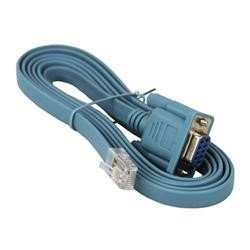

Figure 2.2 Arrangement of DB9 female to RJ45 male cable (WTI, 2013)
2.3 Switch and Router
A switch is a device that can connect between computers, between local networks, and between computers and local networks. In OSI (Open Systems Interconnection) the reference model works at layer 2, namely datalink. Switches have multiple ports and work by forwarding incoming frames from a port to a destination port. The switch stores the hardware address and port location of the connected devices on a port.
Router is a device that connects between networks (currently between switches). In OSI (Open Systems Interconnection) the reference model works at layer 3, namely the network. Router works based on network address. The router determines the path to go to other networks (Gebali, 2008).
2.4 IP (Internet Protocol) Address
IP address or translated as IP address defines a host or a router to the Internet network, is a binary series of numbers. Computer networks and Internet networks today use IP addresses to indicate the identity of a device. This address is used as the identity of the data sender and receiver. Therefore IP addresses must be unique and universal. Currently there are 2 versions of IP, namely IP version 4 and IP version 6.IPV4 consists of 32 bits and is written in binary or decimal form, while IPV6 consists of 128 bits and is written in binary or hexadecimal form, currently used is IPV4, IPV6 for the future.
IPV4 is written with a subnet mask or prefix. Writing in decimal divided by byte or 8 bits (xxxxxxxx.xxxxxxx.xxxxxxx.xxxxxxx).
Example 2.1
An IP address 192.168.0.1 (11000000.10101000.00000000.00000001) 255.255.255.0 (11111111.1111111.1111111.00000000). Writing in the prefix is 192.168.0.1/24 (x.x.x.x/n), the number 24 represents the number of bits 1 in the subnet mask. Therefore, the author of the subnet mask can only be divided into 2 poles, namely the left side of the number 1, and the right part of the number 0 (it cannot be random).
The subnet mask shows the number of hosts in a network, shows the network ID (identity), and the host ID. To find the network ID for an IP address, perform the AND operation on the given subnet mask.
Example 2.2
From example 2.1 192.168.0.1 (11000000.10101000.00000000.00000001) 255.255.255.0 (11111111.1111111.1111111.00000000), 11000000.10101000.00000000.00000001 AND 11111111.1111111.1111111.00000000 result are 11000000.10101000.00000000.00000000 where 192.168.0.0 is network ID, and host is 192.168.0.1.
IP addresses can be class or classless. If it is a class, it is divided into 5 classes, namely A, B, C, D, and E. What is used in general is A - C, while D is for multicast and E experimentally, and is used for future needs (Sutanta, 2005). Here are 2 tables showing the class and a table regarding the prefix.
Table 2.1 IP address class (Sutanta, 2005)
| Class | Subnet | Allocation |
|---|---|---|
| A | 255.0.0.0 | 0.0.0.0 – 127.255.255.255 |
| B | 255.255.0.0 | 128.0.0.0 – 191.255.255.255 |
| C | 255.255.255.0 | 192.0.0.0 – 223.255.255.255 |
| D | - | 224.0.0.0 – 239.255.255.255 |
| E | - | 240.0.0.0 – 255.255.255.255 |
Table 2.2 Prefix (Sutanta, 2005)
| /n | Subnet | /n | Subnet | /n | Subnet | /n | Subnet |
|---|---|---|---|---|---|---|---|
| /1 | 128.0.0.0 | /9 | 255.128.0.0 | /17 | 255.255.128.0 | /25 | 255.255.255.128 |
| /2 | 192.0.0.0 | /10 | 255.192.0.0 | /18 | 255.255.192.0 | /26 | 255.255.255.192 |
| /3 | 224.0.0.0 | /11 | 255.224.0.0 | /19 | 255.255.224.0 | /27 | 255.255.255.224 |
| /4 | 240.0.0.0 | /12 | 255.240.0.0 | /20 | 255.255.240.0 | /28 | 255.255.255.240 |
| /5 | 248.0.0.0 | /13 | 255.248.0.0 | /21 | 255.255.248.0 | /29 | 255.255.255.248 |
| /6 | 252.0.0.0 | /14 | 255.252.0.0 | /22 | 255.255.252.0 | /30 | 255.255.255.252 |
| /7 | 254.0.0.0 | /15 | 255.254.0.0 | /23 | 255.255.254.0 | /31 | 255.255.255.254 |
| /8 | 255.0.0.0 | /16 | 255.255.0.0 | /24 | 255.255.255.0 | /32 | 255.255.255.255 |
If the subnet mask is deepened, the subnet mask can determine the number of IP addresses on a network. The number of IP addresses can be calculated from bit 1 on the right combined with all bits 0 in the subnet mask.
Example 2.3
255.255.255.0 (11111111.1111111.1111111.00000000), then the number of IP addresses = 10000000(2) is 256(10), 255.255.255.224 (11111111.1111111.11111111.11100000), then the number of IP addresses = 100000(2) is 32(10).
Of all IP addresses in a network, the first IP address is used as a network ID, the last IP address is used as a broadcast ID, and if it is a WAN (Wide Area Network) network, one more IP address is needed as a gateway (to another network), usually an address after the network ID.
Example 2.4
192.168.0.1 (11000000.10101000.00000000.00000001) 255.255.255.0 (11111111.1111111.1111111.00000000), then if 11000000.10101000.00000000.00000001 AND 11111111.1111111.1111111.00000000 result is 11000000.10101000.00000000.00000000 is 192.168.0.0 is a network ID, with the host identity 192.168.0.1, with the subnet mask 255.255.255.0 (11111111.1111111.1111111.00000000), then the total number of IP addresses is 10000000 (2) = 256 (10), the first address 192.168.0.0 as the network ID and the last address is 192.168.0.255 as the broadcast ID, and can be selected from 192.168.0.1 - 192.168.0.254 as the gateway, and the rest can be used for the host (Inixindo, 2005). For further exploration, please see the following table.
Table 2.3 Example of IP address management
| IP address | Subnet Mask | Network ID | Gateway | Available Host ID | Broadcast ID |
|---|---|---|---|---|---|
| 10.17.22.45 | 255.0.0.0 | 10.0.0.0 | 10.0.0.1 | 10.0.0.2 - | 10.255.255.255 |
| 10.255.255.254 | |||||
| 172.16.35.5 | 255.255.0.0 | 172.16.0.0 | 172.16.0.1 | 172.16.0.2 - | 172.16.255.255 |
| 172.16.255.254 | |||||
| 172.16.35.5 | 255.255.248.0 | 172.16.32.0 | 172.16.32.1 | 172.16.32.2 - | 172.16.39.255 |
| 172.16.39.254 | |||||
| 192.168.10.22 | 255.255.255.0 | 192.168.10.0 | 192.168.10.1 | 192.168.10.2 - | 192.168.10.255 |
| 192.168.10.254 | |||||
| 192.168.10.22 | 255.255.255.224 | 192.168.10.0 | 192.168.10.1 | 192.168.10.2 - | 192.168.10.31 |
| 192.168.10.30 |
In conclusion, the fewer the number of bits 1 in the subnet mask, the greater the number of hosts and the less the number of network IDs, and vice versa.
2.5 VLAN (Virtual Local Area Network)
A VLAN is a group of devices on 1 or more LANs that are configured to communicate as if they are connected to the same cable, where in fact they are on different LAN segments. VLANs are based on logic rather than physics, because they are flexible.
VLAN defines a broadcast domain at layer 2. Broadcast domain is a set of devices that will receive broadcast frames from any device. Layer 2 Switches create broadcast domains based on switch configurations. Switches are multiport bridges that can create multiple broadcast domains. One VLAN can be a broadcast domain. VLANs cannot communicate with each other because they are in different broadcast domains. To connect between VLANs it is necessary to use a router or layer 3 switch (Cisco, 2004).
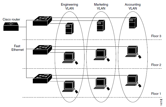
Figure 2.3 Example VLAN (Cisco, 2004)
2.6 Static Route and RIP (Routing Information Protocol)
Static Route is a permanent routing mechanism. The path to a network on a router device is determined directly by the administrator. In the static route setting of a router, it is the next hop when it goes to a network.
RIP is a dynamic route, which is a routing mechanism that varies with time and is flexible. RIP adopts a distance-vector protocol where each router will provide information to neighboring routers about the path connected to the router. From this the router will estimate the distance of all the paths to reach other networks. After that the router will determine its own path based on the shortest distance according to router estimates from the results of exchanging information between neighboring routers (Stallings, 1998).
2.7 NAT (Network Address Translation)
IPV4 is running low, meaning that most of it is already in use around the world. Therefore IPV6 was developed. While waiting for IPV6 to be implemented there is a solution to save IP addresses in version 4, namely NAT. IPV4 addresses are classified into 2 types, namely private IP and global IP. Global IP is an IP address that is only owned by 1 device worldwide and is known in the Internet network. Meanwhile, private IP is an unknown IP address on the Internet network and is free to use by any device so that the owner can be more than 1. The private IP is 10.x.x.x 255.0.0.0, 172.16.x.x 255.255.0.0, and 192.168.x.x 255.255.255.0. Whereas 127.x.x.x 255.0.0.0 is used as the loopback. In addition, it is a global IP address (Inixindo, 2005).
NAT works by translating private IP to global IP and vice versa. For example a host array has private IP 192.168.10.2 - 192.168.10.254 255.255.255.0 and exits via router, gateway 192.168.10.1 255.255.255.0 which can NAT with global IP 202.130.0.5 255.255.255.0, for example to Google DNS 8.8.8.8 255.0.0.0. Then packets out of 192.168.10.2 - 192.168.10.254 will be translated to 202.130.0.5 before sending to 8.8.8.8. After that 8.8.8.8 will reply with the destination IP address 202.130.0.5, after which the router converts to the destination IP address to 192.168.10.x, depending on the sender (Peterson, 2003).
2.8 Telnet
Telnet is an application that works at OSI layer 7, which is an application that can perform remote login, which is entering a device using another computer. Telnet is very useful for remote work, which should come to the location of the device to enter the system, with telnet entry to the system can be done remotely. Telnet transmits data without encryption and is opened on port number 23 (Burgess, 2004).
Chapter 3 Configuration of the Badung Regency Government ICT Network
3.1 Introduction
The ICT network configuration in this report is the ICT configuration in the Badung Regency Government. ICT network configuration includes IP address addressing, VLAN identity allocation, debugging, routing, remote login, and NAT. The port usage on the device is also determined. The physical form of the configured tools can be seen in section 3.3 Tools and Materials in Figure 3.1 and Figure 3.2. IP addressing, port used, and VLAN can be seen in section 3.4 Configuration Plan.
3.2 Place and time
The configuration was carried out in Building 10, namely the Central Government of Badung Regency Transportation and Information Agency from 4 September 2012 to 8 September 2012.
3.3 Tools and Materials
Table 3.1 Tool
| Tool | Description |
|---|---|
| Laptop | Complete hardware along with female RJ45 PCI ethernet and USB female. Software required USB - RS232 driver, Telnet Client, TFTP Server, Serial Terminal, and Cisco Packet Tracer. |
| USB – RS232 converter | If the laptop or computer is not equipped with RS232 male. |
| RS232 female – RJ45 male | As a Cisco console cable for configuring the device. |
| Kabel UTP/ ethernet coaxial cable | To perform configuration testing |
| Pin RJ45 | The end of the UTP cable |
| Crimping Pliers | To connect RJ45 pin to UTP cable |
| Fiber Optic Cables and their connectors | Connection of all buildings to building 10 |
Table 3.2 Materials
| Material | Amount |
|---|---|
| Cisco Multilayer Switch cat4500e | 1 |
| Cisco Switch c3750e | 12 |
| Cisco ASA c2900 | 1 |
| Mikrotik | 1 |
| Cisco Router 2900 series | 1 |
| Modem | 1 |
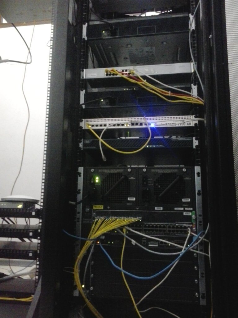
Figure 3.1 Multilayer Switch cat4500e, ASA, Mikrotik, Router 2900 from bottom to top
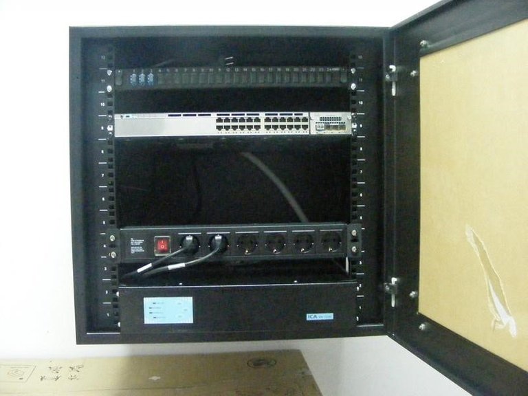
Figure 3.2 Switch C3750e in each building
3.4 Configuration Plan
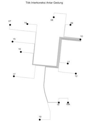
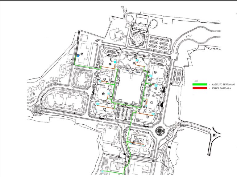
Figure 3.3 Network topology map
Table 3.3 Local network configuration
| Building | IP Switch | VLAN |
|---|---|---|
| 7 | 172.16.0.7/24 | |
| DPRD Secretariat | 10 | |
| 8 | 172.16.0.8/24 | |
| The Regional Secretariat | 11 | |
| 9 | 172.16.0.9/24 | |
| Office of Highways and Irrigation | 12 | |
| Copyright Office | 13 | |
| 10 | 172.16.0.10/24 | |
| The Transportation Department of Communication and Informatics | 14 | |
| Industry and Trade SME Cooperative Office | 15 | |
| 11 | 172.16.0.11/24 | |
| Department of Agriculture, Plantation and Forestry | 16 | |
| Department of Animal Husbandry, Fisheries and Marine | 17 | |
| 12 | 172.16.0.12/24 | |
| Social and Workers Agency | 18 | |
| Public Health Office | 19 | |
| Family Planning and Family Welfare Office | 20 | |
| 14 | 172.16.0.14/24 | |
| Regional Civil Service Agency and Education and Training | 21 | |
| Regional Development Planning Agency and R&D | 22 | |
| Inspectorate | 23 | |
| 15 | 172.16.0.15/24 | |
| National Political and Community Protection Agency | 24 | |
| Office of Women's Empowerment | 25 | |
| Civil Service Police Unit | 26 | |
| 16 | 172.16.0.16/24 | |
| Department of Sanitation and Gardening | 27 | |
| Environmental Agency | 28 | |
| Village Community Empowerment Agency and Pemdas | 29 | |
| 17 | 172.16.0.17/24 | |
| Department of Youth Education and Sports | 30 | |
| Government Tourism Office | 31 | |
| Department of Culture | 32 | |
| 18 | 172.16.0.18/24 | |
| Department of Population and Civil Registration | 33 | |
| 18a | 172.16.0.118/24 | |
| Department of Revenue / Pesedahan Agung | 34 | |
| 19 | 172.16.0.19/24 | |
| LPSE | 35 |
Table 3.4 VLAN configuration
| INTERFACE | IP ADDRESS | 3750 (Trunk) | 3750 (Access) | PHYSICAL INTERFACE Catalysyt 4507R |
|---|---|---|---|---|
| VLAN 10 | 172.16.10.1 / 24 | Gi1/1/1 | Gi 1/0/1 - Gi 1/0/4 | Gi 1/1 |
| VLAN 11 | 172.16.11.1 / 24 | Gi1/1/1 | Gi 1/0/1 - Gi 1/0/4 | Gi 1/2 |
| VLAN 12 | 172.16.12.1 / 24 | Gi1/1/1 | Gi 1/0/1 - Gi 1/0/2 | Gi 1/3 |
| VLAN 13 | 172.16.13.1 / 24 | Gi1/1/1 | Gi 1/0/3 - Gi 1/0/4 | Gi 1/3 |
| VLAN 14 | 172.16.14.1 / 24 | Gi 2/13, 2/14 | ||
| VLAN 15 | 172.16.15.1 / 24 | Gi 2/15, 2/16, 2/17, 2/18, 2/19, 2/20 | ||
| VLAN 16 | 172.16.16.1 / 24 | Gi1/1/1 | Gi 1/0/1 - Gi 1/0/2 | Gi 1/4 |
| VLAN 17 | 172.16.17.1 / 24 | Gi1/1/1 | Gi 1/0/3 - Gi 1/0/4 | Gi 1/4 |
| VLAN 18 | 172.16.18.1 / 24 | Gi1/1/1 | Gi 1/0/1 - Gi 1/0/2 | Gi 1/5 |
| VLAN 19 | 172.16.19.1 / 24 | Gi1/1/1 | Gi 1/0/3 - Gi 1/0/4 | Gi 1/5 |
| VLAN 20 | 172.16.20.1 / 24 | Gi1/1/1 | Gi 1/0/5 - Gi 1/0/6 | Gi 1/5 |
| VLAN 21 | 172.16.21.1 / 24 | Gi1/1/1 | Gi 1/0/1 - Gi 1/0/2 | Gi 1/6 |
| VLAN 22 | 172.16.22.1 / 24 | Gi1/1/1 | Gi 1/0/3 - Gi 1/0/4 | Gi 1/6 |
| VLAN 23 | 172.16.23.1 / 24 | Gi1/1/1 | Gi 1/0/5 - Gi 1/0/6 | Gi 1/6 |
| VLAN 24 | 172.16.24.1 / 24 | Gi1/1/1 | Gi 1/0/1 - Gi 1/0/2 | Gi 1/7 |
| VLAN 25 | 172.16.25.1 / 24 | Gi1/1/1 | Gi 1/0/3 - Gi 1/0/4 | Gi 1/7 |
| VLAN 26 | 172.16.26.1 / 24 | Gi1/1/1 | Gi 1/0/5 - Gi 1/0/6 | Gi 1/7 |
| VLAN 27 | 172.16.27.1 / 24 | Gi1/1/1 | Gi 1/0/1 - Gi 1/0/2 | Gi 1/8 |
| VLAN 28 | 172.16.28.1 / 24 | Gi1/1/1 | Gi 1/0/3 - Gi 1/0/4 | Gi 1/8 |
| VLAN 29 | 172.16.29.1 / 24 | Gi1/1/1 | Gi 1/0/5 - Gi 1/0/6 | Gi 1/8 |
| VLAN 30 | 172.16.30.1 / 24 | Gi1/1/1 | Gi 1/0/1 - Gi 1/0/2 | Gi 1/9 |
| VLAN 31 | 172.16.31.1 / 24 | Gi1/1/1 | Gi 1/0/3 - Gi 1/0/4 | Gi 1/9 |
| VLAN 32 | 172.16.32.1 / 24 | Gi1/1/1 | Gi 1/0/5 - Gi 1/0/6 | Gi 1/9 |
| VLAN 33 | 172.16.33.1 / 24 | Gi1/1/1 | Gi 1/0/1 - Gi 1/0/4 | Gi 1/10 |
| VLAN 34 | 172.16.34.1 / 24 | Gi1/1/1 | Gi 1/0/1 - Gi 1/0/4 | Gi 1/11 |
| VLAN 35 | 172.16.35.1 / 24 | Gi1/1/1 | Gi 1/0/1 - Gi 1/0/4 | Gi 1/12 |
Table 3.5 Internet Configuration
| Device | IP Address | IP Type | Interface |
|---|---|---|---|
| CiscoMultilayer Switch cat4500e OUT | 172.16.128.1/24 | Local | Gi 2/48 |
| Connect To | |||
| Cisco ASA 2900IN | 172.16.128.2/24 | Local | Gi 0/0 |
| Cisco ASA 2900OUT | 192.168.101.1/24 | Local | Gi 0/1 |
| Connect To | |||
| Mikrotik IN | 192.168.101.2/24 | Local | e1 |
| Mikrotik OUT | 192.168.253.1/24 | Local | e8 |
| Connect To | |||
| Cisco Router2900 IN | 192.168.253.2/24 | Local | Gi 0/1 |
| Cisco Router2900 OUT | 202.46.10.130/24 | Public | Gi 0/2 |
| Connect To | |||
| Modem | 202.46.10.129/24 | Public | e1 |
| Connect To | |||
| Internet |