It has been nearly a week since I posted Part 1, or anything else for that matter. I've had all kinds of fun with migraines, family matters, and of course, building the LEGO Lamborghini. Yes, it's done, but I have a lot of posts to process now that it no longer distracts me.
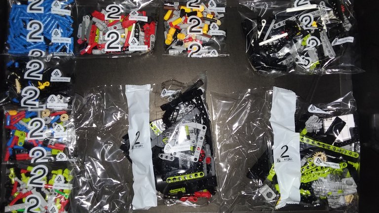
This second large green box contains not only the engine and suspension, but also a series of reinforcement additions to the frame thus far. Step 2 actually took longer than step 1, because the first box also included some components for the rest of the set. This is all part 2 parts.
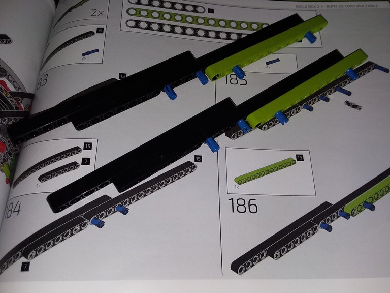
The beginning was a bit mundane. Just some more reinforcement beams.
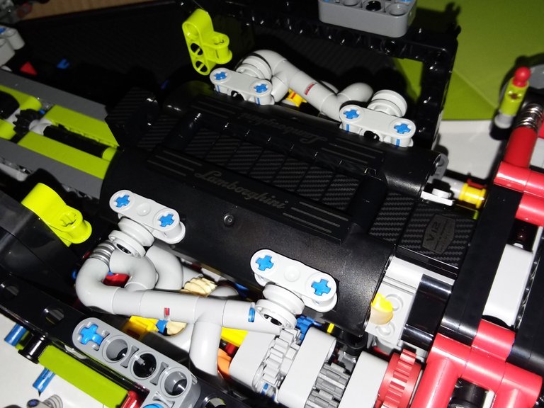
However, we soon come to a really fun bit, and one of the biggest attractions of this model: the engine block. V-12 power!
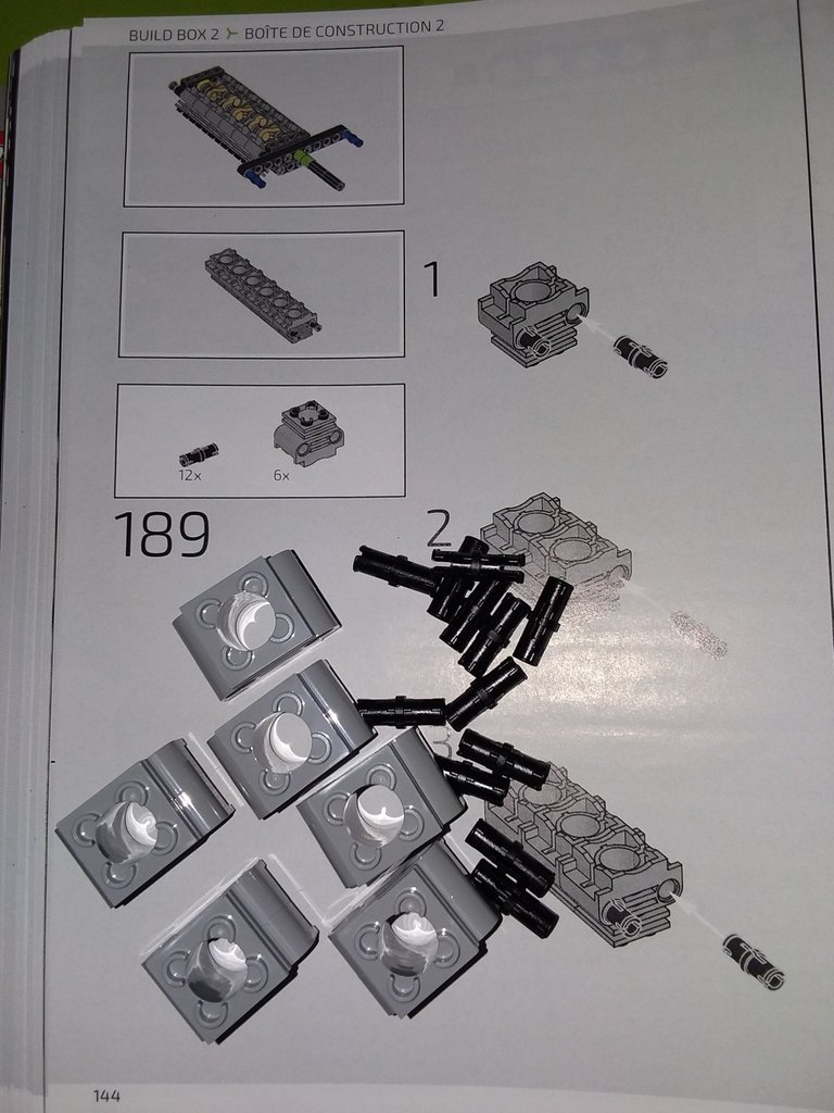
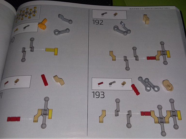
The crankshaft and piston rods are assembled in an alternating pattern, although I am unsure whether this accurately represents the way a real Lamborghini engine functions.
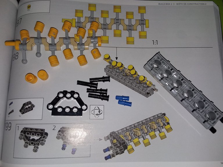
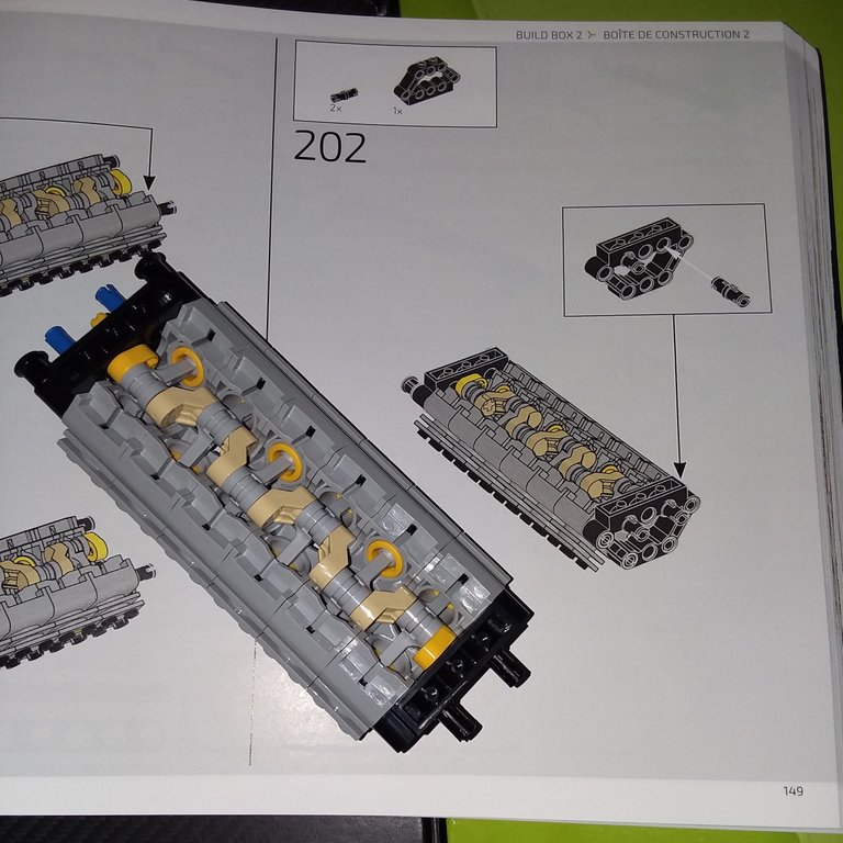
Once the pistons are snapped onto the piston rod ball joints, one row is loaded into a cylinder bank before the second bank is installed to complete the engine block.
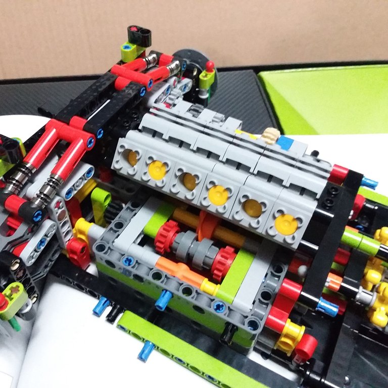
Once it is installed on top of the transmission, it starts to look like a proper car!
On to suspension construction. First up: the front differential assembly.
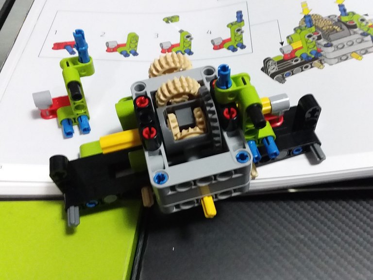
I made a mistake here, and had to correct it later. You may notice I didn't add the flat gray beams to both sides of the front forks here. Oops. That's what happens when you build while tired.
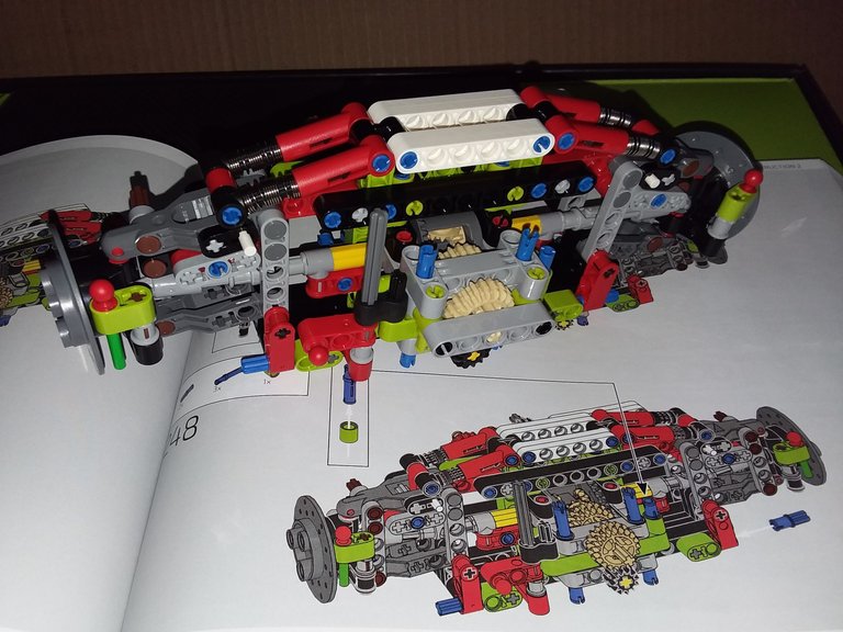
A few more steps and the front suspension is joined to the rear. Now we have a full chassis of sorts!
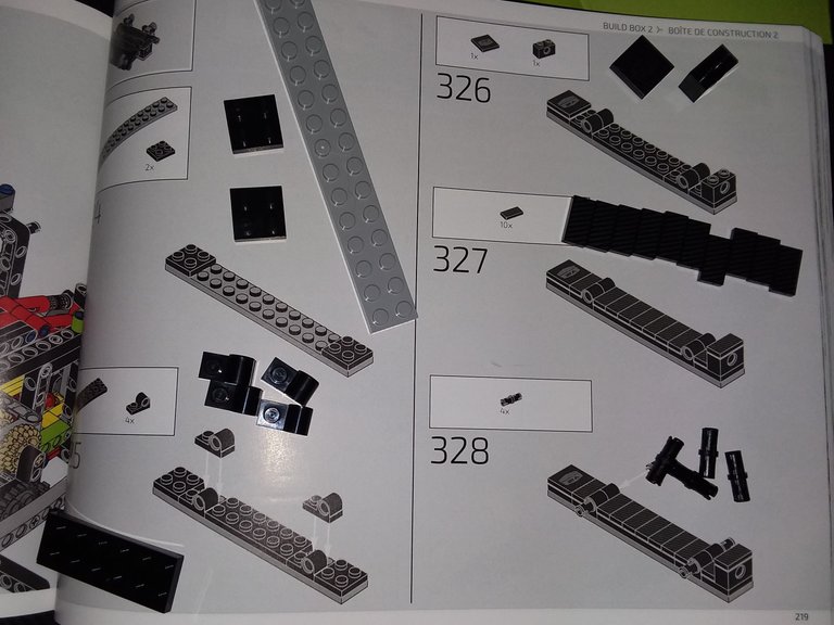
And here we have proper LEGO bricks showing up for the first time at step 324, page 219 of book 1.
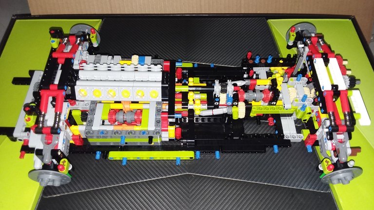
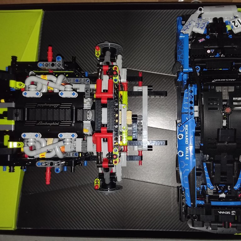
The carbon fiber pattern on the smooth plates doesn't proper;y show in these photos, but it looks good in person. The tubing instructions were a bit convoluted, too. Is this supposed to represent exhaust, turbochargers, or air intakes? I'd have to look up the car itself.
At the end of Part 2, you can see the chassis is almost as wide as the McLaren. Everything about this car is massive.
It'll take a while to compose Part 3. I'll continue my plan to share this post section by section and box by box. There may also be a followup, because I'll need to disassemble it to figure out why the All-Wheel Drive system locks up at all settings. For all I know, I screwed something up way back in Part 1 with that crazy transmission contraption...
Well they certainly look impressively convoluted, representing actual engine parts seems like a reasonable assumption.
That thing looks kind of big unless your other build is small.
The car is massive. Almost 24" long.
I always find this part of technic builds both extremely fun and a little disappointing. The insides are always the most challeneging and fun (those pistons are awesome) but then it all gets covered up and no one ever sees it. But it's coming along very well.