In this article, I will try to show you how to use Arduino so that we can move on to more interesting things. If you ever have any problems or if you want more explanations, don't hesitate to tell me in the comments!
The choice of the card:
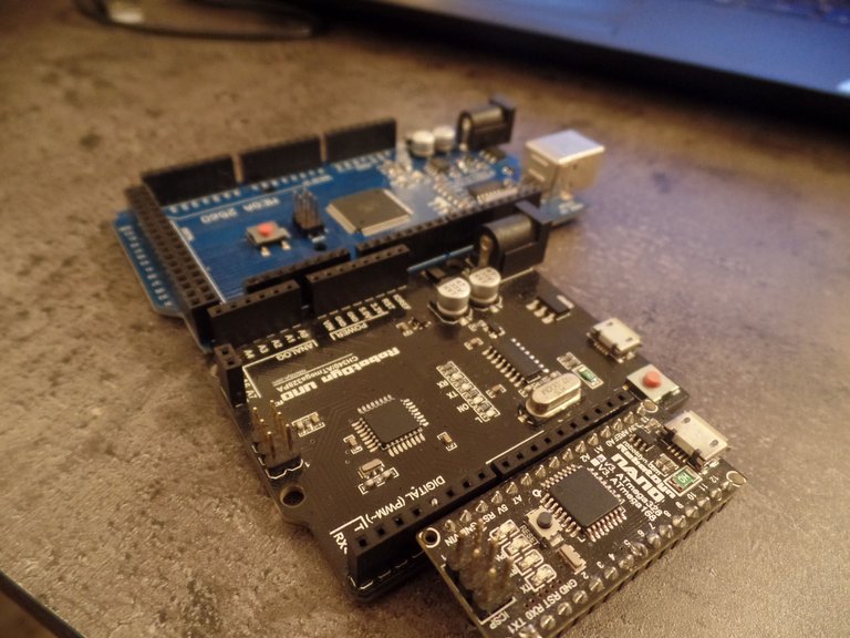
When you choose to work with Arduino (if you haven't already made your choice, you can read this article you can choose between different boards (see the Arduino.cc website for the full list) of which the 3 most known:
- Arduino Uno: Perfect for beginners and practical to use
- Arduino Nano: Compact and breadboard compatible (we'll see below what it means), perfect for prototyping or for small spaces.
- Arduino Mega: More GPIO if your project requires it, a Mega saves you from having to take several cards.
If these little descriptions are not enough for you to make your decision, feel free to take a look at this page and the product sheets available on [Arduino.cc](arduino. cc).
And to finish this first part, a little point about clones. As I explained to you in the first article (Raspberry Pi vs. Arduino) Arduino is open-source so there are a multitude of manufacturers, so there is a multitude of prices too (and which can vary from $25 for an "official" Arduino UNO card to $2 for a cloned Arduino card in China). I've rarely had problems with clones but the main drawbacks are the delivery times (which can exceed 2 months) and the quality of the after-sales service, so pay attention to the reviews when you buy in China.
Installation of the IDE:
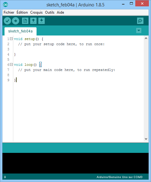
Arduino IDE is a software developed by Arduino to simplify the programming of its cards, it includes everything you need to program, debug and communicate with your card. Installation is easy, whether you are on Windows, Linux or Mac.
To start, go to the download page and check that the selected hardware is yours and download the installer.
Once installed you will be able to use the integrated editor for:
- Write your programs with the text editor,
- Find bugs in your programs,
- Compile your programs (roughly, the compilation turns a "text file" into an executable program),
- Communicate with your Arduino card: to send it a new program or to send/receive information)
- Easily install libraries.
More on the board :
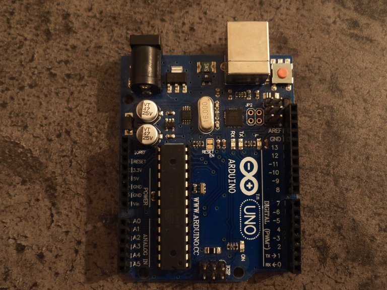
Before I start I will give you some details about the Arduino UNO card.
Two rows of pins on either side of the board allow you to interact with the different components you will use. There are different types of them and they are called this way:
- D0->D13 pins are digital inputs/outputs, i. e. they can be used to read or "write" (apply a potential) of 0V or 5V.
- The pins A0->A5 are analog inputs, these pins can read the value of a voltage varying between 0 and 5V on a resolution of 1024 values (0V = 0 and 5V = 1024) which means that these pins have an accuracy of 4.88mV (5/1024 = 4.88*10^-3 V).
- The power supply pins, located above the analogical pins they allow to power your electrical circuits you will find potentials of 5V, 3.3V, GND (ground), and a VIN pin (for V in, it can be used to power your card, it is an alternative to the USB cable and jack) (we will not use the rest for the moment).
Basic components:
Here is a quick summary of the components we will use for the next 2 examples:
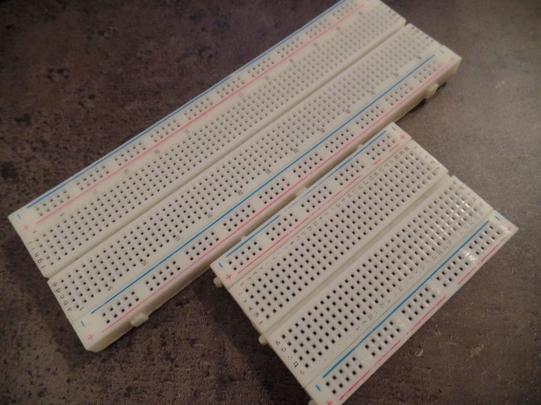
Breadboards:
It's not really a component because breadboards allow making circuits easily without having to solder the different components. They are often used in prototyping phases and come in different sizes:
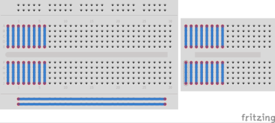
The breadboard holes are connected in a certain way that you will have to keep in mind to make your own assembling:
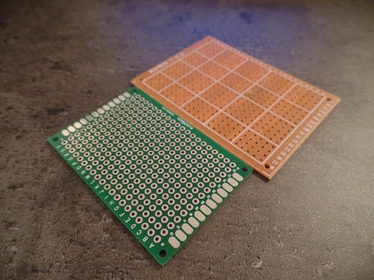
Once the prototyping is done we use this kind of boards to solder the circuit or we draw our printed circuits boards (PCB).
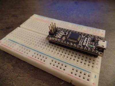
I said in the first part that the Arduino Nano was compatible breadboard, it simply means that you can insert it on a breadboard like this:
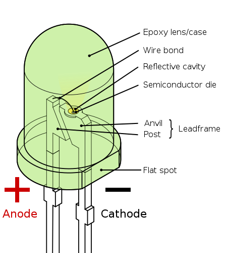
The LEDs:
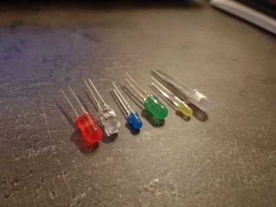
LEDs are components that emit light when a current passes through them. One of the characteristics of an LED is that it can only let the current flow in one direction (from the positive pole called anode to the negative pole called cathode), the other direction block the current.
When used with an Arduino (operating at 5V) a 220 Ohm (minimum) resistor must be added in order not to exceed the permissible current. If the permissible current is exceeded, the LED break and there is a good chance that you will no longer be able to use the pins on which it was plugged in.
Fun Fact: The first LED was discovered in 1907, the first red led was invented in 1962. At that time the choice of colors was rather limited: Red, Yellow or Green. It was not until 1972 that researchers invented blue LEDs (and 1990 to have bright blues), used to create white LEDs and RGB (Red Green Blue) which were used in the backlighting of screens or LCD screens. The researchers who created the blue led even received a Nobel Prize for their discovery. Source 1 and 2
The resistors:
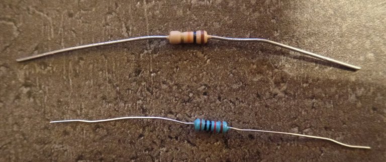
The resistors are components without polarity (you can connect them in any direction you want) and are used to oppose a resistance R (in Ohm, noted Ω) to the current. It is this R that we find in the famous Ohm's law: U = R * I where U is the Voltage in volts (V) and I the current in amperes (A).
One of the peculiarities of resistors is the system used to mark the differents informations on the component, with colored "rings" around the component:
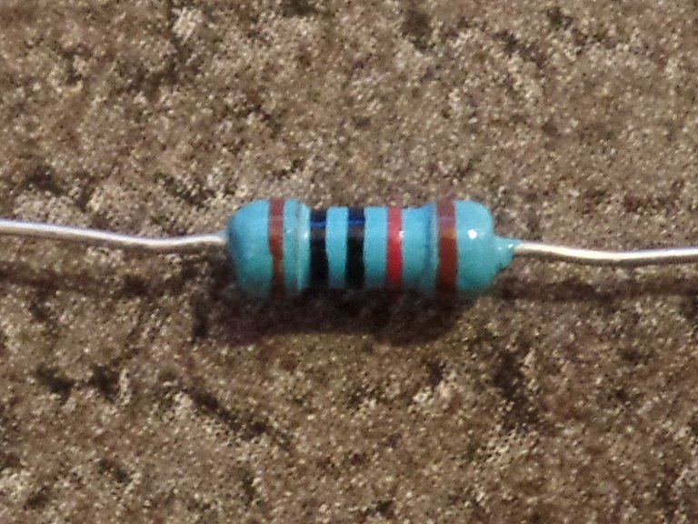
There is a color code, but I don't think it's useful to learn it, use an application to find the different information you write down and remember the colors of the ones you use most often.
Blink:
I think one of the best ways to learn how to program is practice so I move quickly to examples, but reassure you every line is explained. If you need explanations about a particular function, please have a look at Arduino Reference.
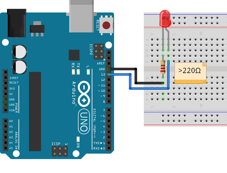
Blink is the electronic equivalent of a "Hello World" in programming, i. e. it's the first thing you do to make sure you understand how it works. The electronic circuit is very simple and consists of connecting a led and a resistor between pins 13 and GND and then creating a program to make it flash.
Diagram:
To find out which way to connect the LED, look at the length of the legs (the longer the positive leg) or the flat present on the negative side.
Program:
You can find the code on Github.
What I call symbol in the above program is a preprocessor, it acts as a constant except that it is replaced at the time of compilation by the value assigned to it. As a result, it takes up less memory space and is perfect for assigning a name to a pin number. And just like constants, symbol names are in capital letters by convention.
Hello World + Serial Interface:
The second example I wanted to give you is a little more advanced Hello World allowing you to see how the serial interface works, which is used to communicate your Arduino with your PC.
Diagram:
For this example, you won't need anything to connect:)
Program:
You can find the program on GitHub.
Make a counter:
And finally here is an example illustrating different functionalities of Arduino. The purpose of this example is to make a counter using a pushbutton that can be set to increment or decrement using the serial interface.
Diagram:
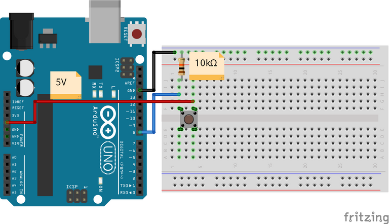
We can see on the diagram that I placed a 10kΩ (10 000Ω) resistor between the digital input (which is also connected to one of the tabs of the button) and the ground, this one is called pull-down and serves to avoid that the input acts like an antenna and catches the parasites (which would distort the measurement).
Program:
You can find the code onGitHub.
I hope that this article will have you more and on this last example, I will tell you soon for a next article.
To go further:
- Tutorials Arduino. cc as well as the examples provided with the IDE
- Arduino projects on Hackster
- Arduino Reference
Sources:
- Arduino. cc and in particularthis page and the examples provided.
- Arduino Reference
- [FR]Course on C -> Preprocessors
- Engineering Science at High School + Electronics course
- Wikipedia: Resitor,LEDs - The First Blue Led
This is a test comment, notify @kryzsec on discord if there are any errors please.
Being A SteemStem Member
Congratulations! This post has been upvoted by SteemMakers. We are a community based project that aims to support makers and DIYers on the blockchain in every way possible. Find out more about us on our website: www.steemmakers.com.
If you like our work, please consider upvoting this comment to support the growth of our community. Thank you.
Awesome intro, review, and info. I love making stuff with Arduino. I will definitely follow and look forward to seeing more.
Thank you ! :)
Congratulations @robotics101! You have completed some achievement on Steemit and have been rewarded with new badge(s) :
Click on any badge to view your own Board of Honor on SteemitBoard.
For more information about SteemitBoard, click here
If you no longer want to receive notifications, reply to this comment with the word
STOPCongratulations @robotics101! You have completed some achievement on Steemit and have been rewarded with new badge(s) :
Click on any badge to view your own Board of Honor on SteemitBoard.
For more information about SteemitBoard, click here
If you no longer want to receive notifications, reply to this comment with the word
STOP