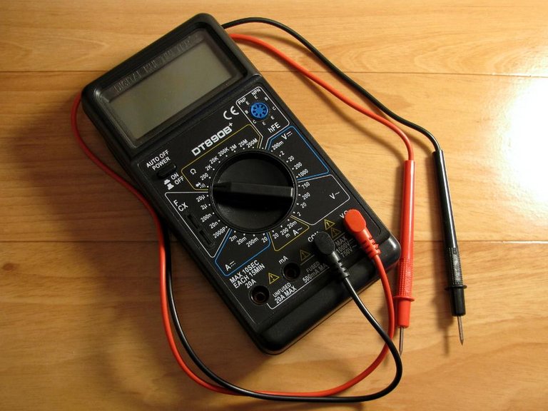
A few days ago, my multimeter stopped working. The multimeter itself is very simple, cheap and worked reliably for several years. And now it does not work. It flashes in digits on the display, shows incorrect values, and flashes with a battery symbol. So we need to replace the battery.
Оригинал на русском опубликован здесь.
Well, if necessary, then we will replace.
And I climbed onto the cabinet, took out the cherished box, where different batteries were carefully stored in advance.
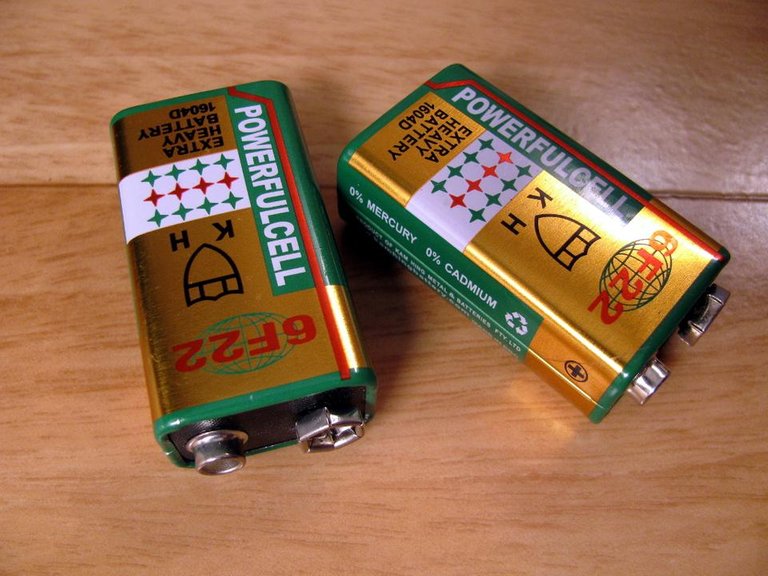
In the same place, in a separate package, there were three “Krones”, this is if in an old, Soviet way.
In the perestroika time, these batteries were called "Corundum".
And at the beginning of the new century, they were from China and were called "Cosmos 9 Volt".
Well, in the West they at all times, it seems to me, were called equally simply - "6F22".
I took one battery and set it.
And turned on.
Does not work.
Changed the second battery, the third.
The same result.
I tried the contacts on the language. We tested the batteries in childhood in this way. Very weakly tingling, but not jerking, nine volts not. I took out an old, arrow tester, measured the voltage - exactly, no more than five to six volts shows the voltage to them.
They are in vacuum packaging, new, never used.
They were bought in advance as a spare.
Over three years of storage.
They are self-discharged.
All three.
And now they are only suitable for disassembly - the connectors and tin boxes will still be useful.
And here I got a little angry.
And after all, not only do you need to change them in the device every six months or a year, but you cannot stock them in advance.
And I lost all desire to again order the next "6F22" on the Internet.
And then I also have to check daily the status of this order in my account.
And wait for notification of receipt a few days on the phone.
And then I have to go after them to the point of delivery of packages, in the cold, over ice, in the middle of winter, and at dusk.
And I looked around.
And I saw a wondrous world, full of mobile devices and gadgets of various, has long been worked on rechargeable batteries.
And they work successfully.
And I decided to add another device to this world, my multimeter.
And make it out of what is at hand.
And descriptions of such miracles and such magic on the Internet is enough.
And what is at hand?
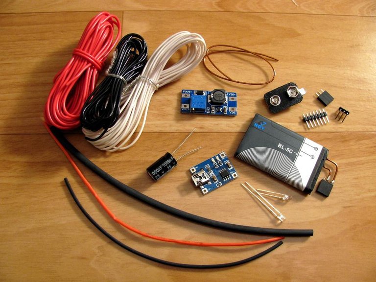
— The BL-5C battery itself, remaining unused from the scaled pocket-sized radio receiver.
I had soldered copper wires with a connector to it earlier, although soldering the contacts of lithium-ion batteries is strongly discouraged due to the danger of overheating and possible fire. The soldering should be carried out literally in one or two instantaneous touching: the contact is tinned with the first touch, the wire is soldered with the second touch. Wait until the battery has cooled down between touching. Better yet, use a battery without a case, such as one whose wires are already soldered.
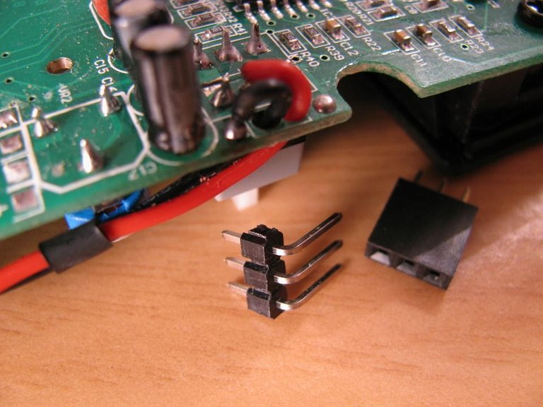
— Straight connector for three contacts - the usual single-row straight connector for 40 contacts is taken and, as necessary, parts of the desired length break off.
The counter part to it, if necessary, is similarly cut off from the 40-pin long connector. Or you can buy it separately.
— Three-pin corner connector - also breaks off from a 40-pin, but already an angular connector.
— The charger device on the chip TP4056, where do without it?
— MT3608 voltage up-converter device board.
— Electrolytic capacitor 1000 microfarad x 25V for smoothing pulsations at the output of the converter.
— A pair of three-millimeter LEDs in a transparent case for indication. A ruby-red and emerald-green glow. I immediately took a set of LEDs, but you can choose separately.
— Connecting mounting wires, preferably multicolored, to make it easier to figure out where that is connected.
— Millimeter thick copper wire in enamel insulation, to give the structure rigidity - we will clean it and tin, then solder.
— Connector from one of the faulty "6F22".
— Power switch - not shown here, we will try to use the native one, from the multimeter itself.
— Thermal shrinkage for insulation of wires and connections, as well as for the connection of individual wires into bundles.
And if I decided, then I have to do it.
But first I need to check whether all this can fit in the box of a multimeter.
In my multimeter "Resanta DT890B +", as it turned out, can, although not in any part, we need to select the location.
It will all be located on the surface of the back cover of the case.
Here is an illustrative scheme of the connection modules.

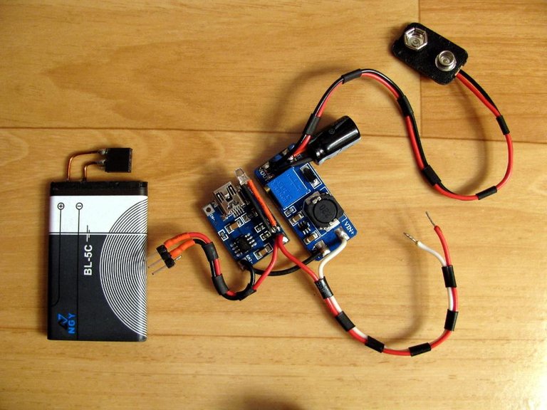
We assemble the test bench, trying it on the back cover, immediately taking into account the future location of the components in the case, so as not to re-solder.
It looks like this.
We solder ordinary LEDs instead of SMD-LEDs to the charger board. They are connected according to the scheme with a common anode. It would be possible to leave the initial indication, but then the process of charging the battery would not be visible outside the closed case.

The multimeter's power switch itself has two groups of contacts, both are used.
We can leave the inclusion of a multimeter only on one of them. To do this, we will have to cut a couple of printed tracks on the board and solder the positive red wire to another contact of the switch.
As it turned out later, in some models of multimeters such alteration can affect the auto-off circuit (switching the time-delaying capacitor), but there’s no auto-off function in my multimeter, so everything is fine.
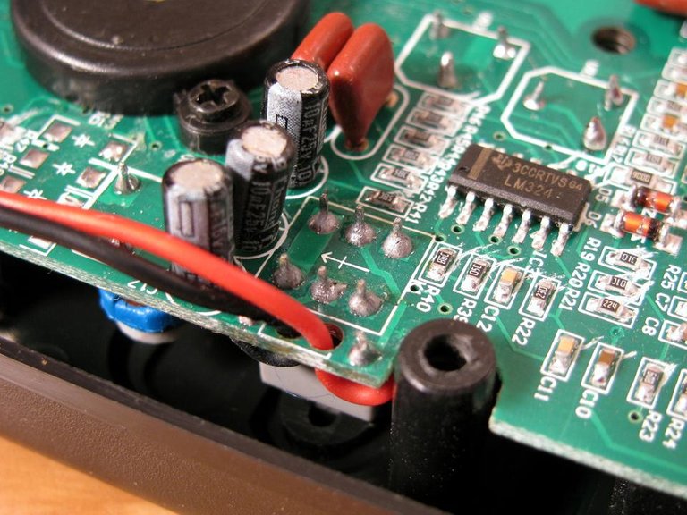
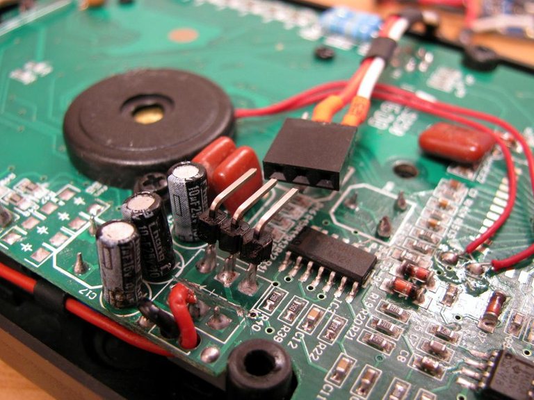
We cut two printed tracks between the switch contact groups.
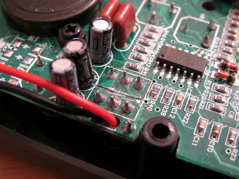
Printed tracks to the contacts of the switch are also laid on the reverse side of the printed circuit board.
To make sure of this, the power switch itself had to be unsoldered.
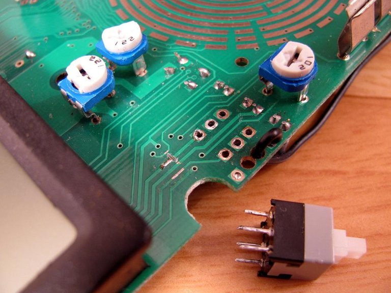
It is seen that both the conductor from the switch go somewhere under the indicator of the multimeter.
Where exactly they go, I did not find out (if necessary, the schematic diagram for this model of a multimeter can be found here). Since I did not want to unsolder the indicator.
Simply, at my own risk, I also cut the track going to the switch contact group on the inside of the board and connected it with a jumper to the track going to the switch contact group closer to the outside of the board.

Then I soldered the power button, as it was before. To solder it back, we need to set the button with the correct side, otherwise it may happen that the multimeter will turn on when the button is released, and not when pressed, as it should be.
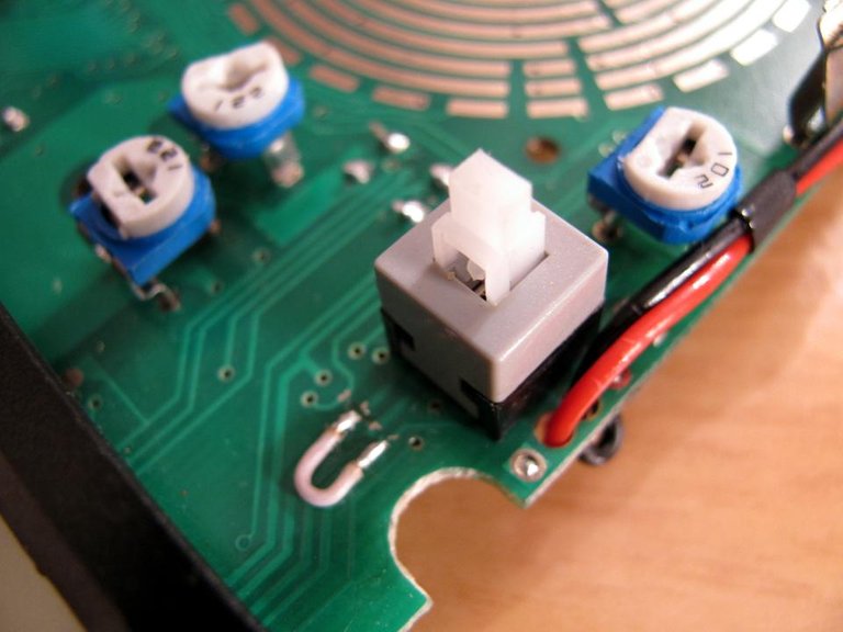
After corrections, both groups of contacts must be electrically isolated from each other, both when pressed and when the button is released.
The released group of contacts (closer to the center of the board) we will give for switching on the converter.
The inclusion of the multimeter itself will be carried out by a group of contacts located closer to the edge of the board.
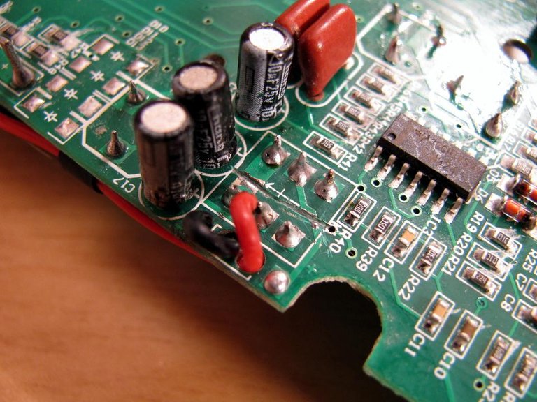
In this case, the red (positive) power wire must be soldered to the middle contact of this group. So, as shown here.
However, if the standard switch cannot be used in this way (for example, due to a different multimeter model, another printed circuit board pattern or other switch design), we can always put an additional button.
But then we need to remember to turn the additional button on and off, as well as the main button on the multimeter.
If this is difficult, there is another option - to use a reed switch with contacts for closure together with a magnet glued to the pusher of the main button. But I did not reach it.
For convenient connection of the power source to the multimeter to the free contacts of the switch, we additionally solder the angular connector.
We solder the mating connector to the white-red wire from our alternative source.
It looks something like this.
We turn on the test bench and measure the constant voltage at the output of the MT3608 converter without a load (connector "6F22" is not yet connected).
The trim resistor on the converter board, we set the voltage to nine Volts.
The battery must be fully charged in advance.
Then we connect the multimeter's power connector, turn on the multimeter and measure the voltage at the output of the converter again. If the voltage under the load has become lower, again on the trim resistor we expose 9 Volts.

And then we pay attention to our multimeter itself.
We try to measure something with it, for example, the resistance of a resistor or simply the resistance of short-circuited probes.
If the readings are similar to the truth - for a resistor it shows its resistance (taking into account the tolerance or accuracy class of the resistor), for short-circuited probes - zero or Ohm's fraction - which means we can put our device into the multimeter case.
To do this, in the side wall of the case with thin files we make a hole for the mini-USB connector for the charger, next to it we drill two round holes for the indicator LEDs (one above the other).

We place a test stand in the box of a multimeter.
In this case, we must make sure that the components of our alternative power supply circuit do not interfere with the elements of the multimeter itself and do not close with them.
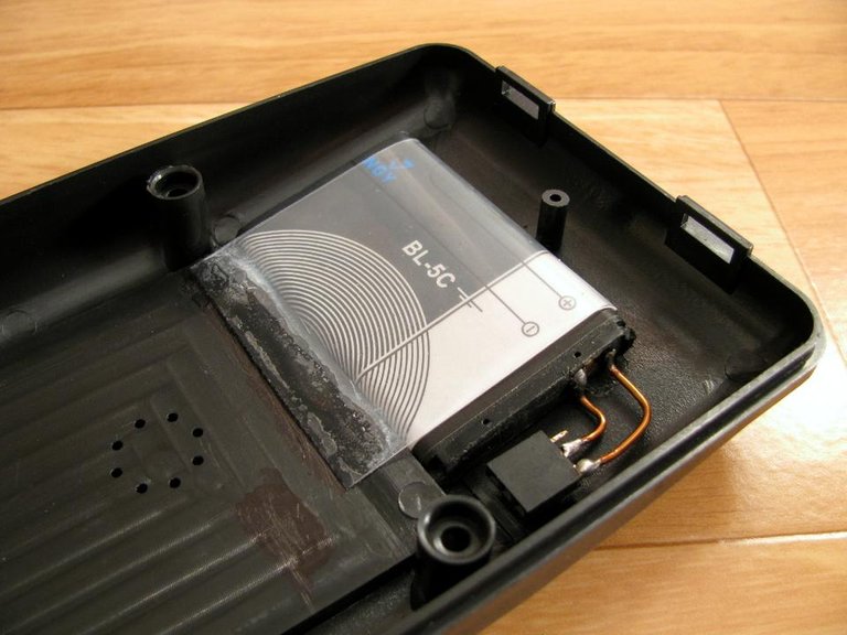
The battery is fixed with a plastic tape, we glue its ends to the back cover of the case.
The tape itself is cut out of the lid of the plastic packaging, for example, from a jar of sour cream or yogurt.
In case of subsequent repair, the tape can be torn off, the battery can be replaced.
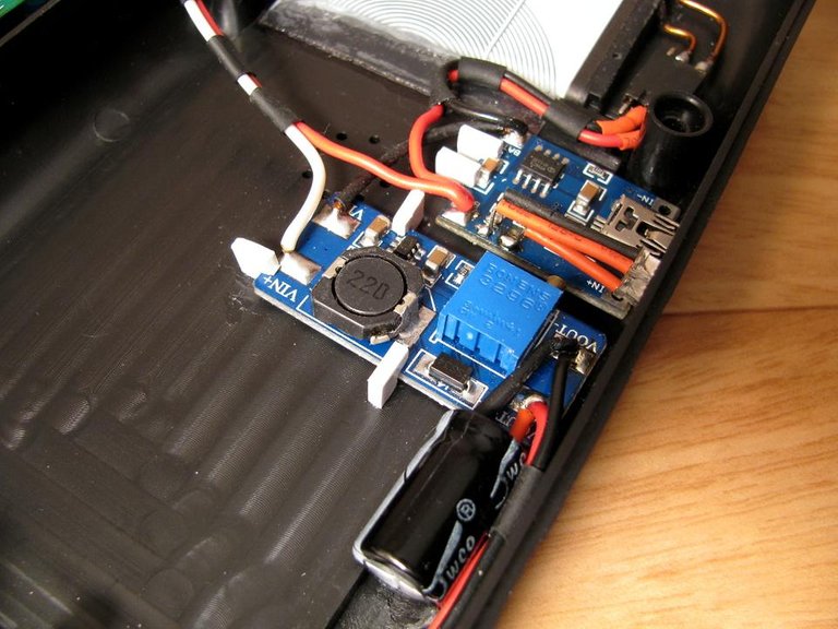
We fix the boards of the charger and the converter in the case with limiting polystyrene slats, gluing them with instant glue to the back cover of the case. Subsequently, if repair is necessary, the slats break out, the boards can be removed, then reinstalled, the slats are glued in again.

I cut the slats from a piece of white polystyrene in the form of squares, 5x5 mm in size. Then, with each square, I carved one of the corners with a file, about 2 mm. And I got hooks - elements for fixing boards.
The LEDs can be fixed in the case with a small drop of instant glue, only it is desirable to put it on the lower side of the LED, so that the lens itself does not dim from the glue.
We finally connect our scheme to the multimeter, close the case, once again check the multimeter in operation.

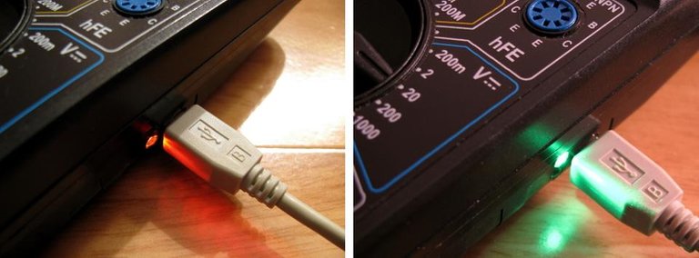
In the process of charging the battery, the ruby-red LED is lit, when charging is complete, the glow changes to emerald green.
Subsequently, we charge the battery from any source that has a five-volt USB output: from a computer, PowerBank, charger or other gadget. In order to ensure the safety of the devices (the multimeter itself and the device you are charging from), as well as your electrical safety, it is advisable not to switch on the multimeter and do not measure anything while it is charging the battery (this may be a controversial point, but I’ll just say).
The time to fully charge the battery with the standard installed current-limiting resistor on the charger board is about an hour.
And here it is, life free from "6F22"!
We use it and enjoy it.
06.01.2019
Sincerely, your @mp42b.
@cleverbot, @automation, @banjo - and how do you meet the holidays?
Congratulations @mp42b! You received a personal award!
Happy Birthday! - You are on the Steem blockchain for 1 year!
Click here to view your Board
Its alove story baby just say yes.
No, this is a story about a piece of iron.
Thanks for the support!
That's not advice. I'm pregnant.
It happens. I'm happy for you!
Aww, thank you!
You're welcome!
I need to know why I am not lovable.
Congratulations @mp42b!
Your post was mentioned in the Steem Hit Parade for newcomers in the following category:
I also upvoted your post to increase its reward
If you like my work to promote newcomers and give them more visibility on the Steem blockchain, consider to vote for my witness!
Thank you so much for sharing this amazing post with us!
Have you heard about Partiko? It’s a really convenient mobile app for Steem! With Partiko, you can easily see what’s going on in the Steem community, make posts and comments (no beneficiary cut forever!), and always stayed connected with your followers via push notification!
Partiko also rewards you with Partiko Points (3000 Partiko Point bonus when you first use it!), and Partiko Points can be converted into Steem tokens. You can earn Partiko Points easily by making posts and comments using Partiko.
We also noticed that your Steem Power is low. We will be very happy to delegate 15 Steem Power to you once you have made a post using Partiko! With more Steem Power, you can make more posts and comments, and earn more rewards!
If that all sounds interesting, you can:
Thank you so much for reading this message!
Thank you, but I do not use Android and iOS mobile apps. Maybe there is a version of Partiko for desktop computers?
This post has received a 3.13 % upvote from @drotto thanks to: @mp42b.
source
Rewarding Your Original Work
With an Upvote
And
Resteem
Well, thank you for your Splat-support!
You are welcome. If you find any undervalued posts feel free to leave a link and we will do our best help curate...it isn’t much but every little bit helps.
Thank you very much!
I'll keep it on mind.
Congratulations! This post has been upvoted from the communal account, @minnowsupport, by mp42b from the Minnow Support Project. It's a witness project run by aggroed, ausbitbank, teamsteem, someguy123, neoxian, followbtcnews, and netuoso. The goal is to help Steemit grow by supporting Minnows. Please find us at the Peace, Abundance, and Liberty Network (PALnet) Discord Channel. It's a completely public and open space to all members of the Steemit community who voluntarily choose to be there.
If you would like to delegate to the Minnow Support Project you can do so by clicking on the following links: 50SP, 100SP, 250SP, 500SP, 1000SP, 5000SP.
Be sure to leave at least 50SP undelegated on your account.
@mp42b, thank you for supporting @steemitboard as a witness.
Click on the badge to view your Board of Honor.
Once again, thanks for your support!
Congratulations @mp42b! You have completed the following achievement on the Steem blockchain and have been rewarded with new badge(s) :
Click here to view your Board
If you no longer want to receive notifications, reply to this comment with the word
STOP@djimirji up!
I'm very happy for you! Many do not have this.
You are welcome!
Always need to learn. And for all, not just computer programs.
Sometimes, but often wrong.