
We can scale a lot in our world.
Including pocket radio receivers.
And it is not only about physical dimensions or quantity. We can also scale the functionality.
And that's what we'll do.
Once I posted an article about a pocket radio in my blog:
Some time later, in the article "Disco from the gift card..." I talked about the use of the MP3 player module.
It's time to combine these two devices into one.
As a result:
- the radio will be loud-speaking, although it will also be possible to use headphones
- the opportunity to listen to your MP3 library, pre-recorded on the memory card
- more functional than the paper card, the case, and nothing will prevent us from carrying it in our pockets and listening anywhere.
This will be our story.
First, let's assemble an FM radio.
For the same, good old, already proven scheme, found several years ago in one of the forums on the Internet.

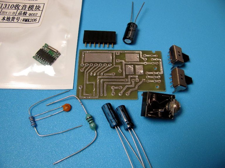
The circuit uses a module with a TJ1310 chip (or AR1310).
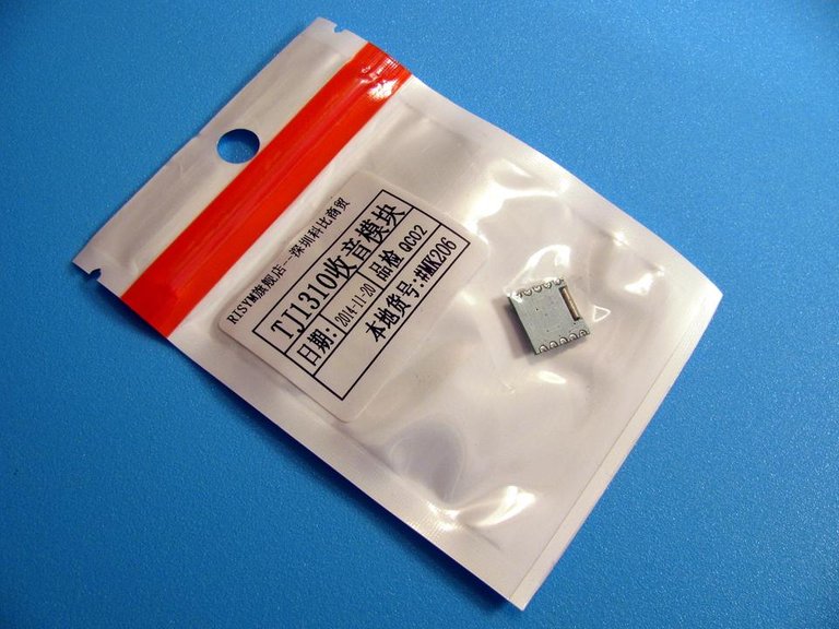
Currently, this module is temporarily absent on the site of tixer.ru, but you can search for it in other amateur radio stores, or on AliExpress.

The picture of the PCB is slightly different from the past, in particular, the receiver control buttons are now on a separate board.
The location of the parts on the PCB of the receiver.
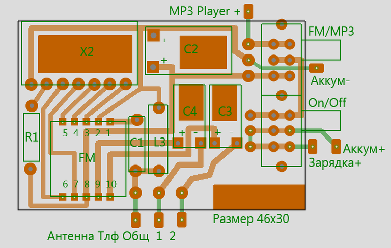
This is a drawing of the receiver PCB.
(Its original size is 46x30 mm; a part of the surface was later cut off for placement in the case).

Here is the location of the elements on the control board. These are five mini buttons and seven pins of a single row PLS-40 connector with a 2.54 mm pitch. Plus a pair of wire jumpers.
The green numbers in the figure indicate the numbers of the IC pins to which the control board is connected through the corresponding pins of the connector.
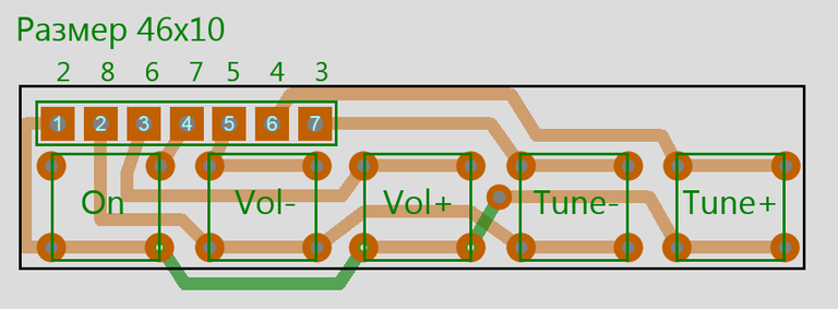
This is a drawing of an additional board with control buttons.
The original size was 46x10 mm, later I had to cut the board to 46x9 mm and add an extra wire jumper.

For the manufacture of printed circuit boards, we will use the simple (very simple) and reliable (with some dexterity) method LUT (laser-iron technology).
Cut a piece of one-sided foil glass fiber from the original, specified size, and clean the burrs at the edges.
With a school eraser we will clean the surface of the foil blanks to a samovar gloss. Try not to touch in the foil with your fingers.
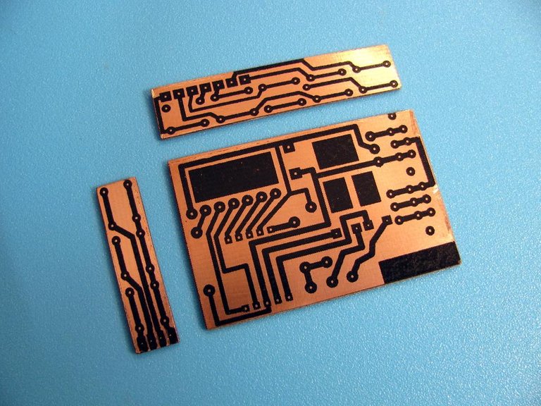
Copy the pictures with the drawings from this article into a text or graphics editor, for example in MS Word, set the initial required size for them there, put some copies of the images on an A4 sheet to choose the best one later.
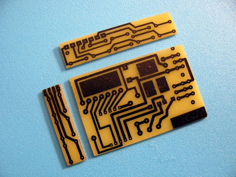
Now let's take one sheet of lemon-yellow paper of a wonderful thermal transfer paper from very distant China and print our picture with a maximum toner density and the toner saving mode disabled on a laser printer. We print on the glossy side of the surface of thermal paper.
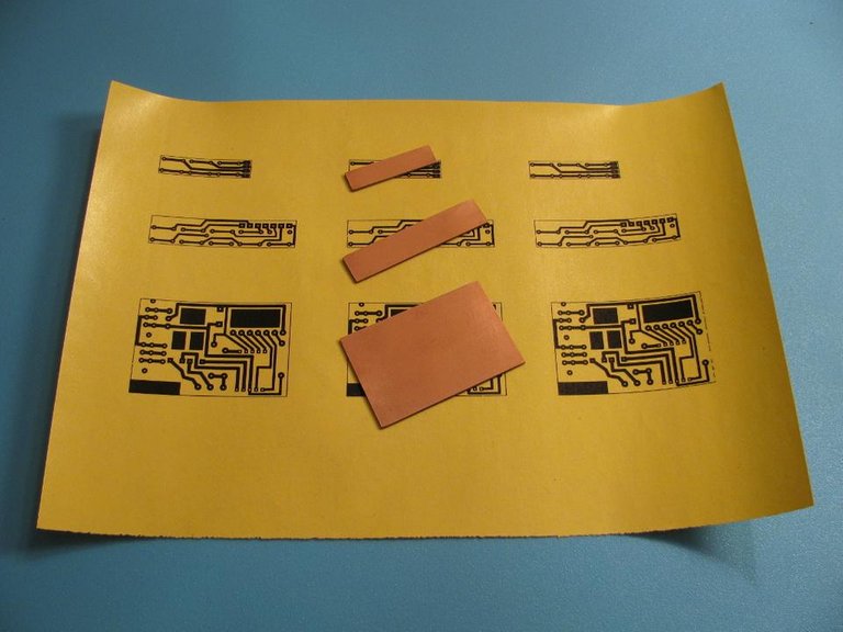
(The third printed circuit board from this photo is intended to accommodate the control buttons of the MP3 player, but more on that later).
We will select the best printed copy and carefully, trying to keep the toner layer from thermal paper not to crumble, cut it with scissors.
Further various options are possible, I will describe my method.
In any case, you need a well-heated iron.
Put our decal on an even layer of several old newspapers with toner printed up. On top of it we place the PCB blank down with foil. Align them with each other. Gently press this sandwich with a hot iron for 5-6 seconds, so that the fiberglass laminate warms up and the decal sticks to it.
Then we turn the sandwich with a yellow paper up and over, but for 15-20 seconds we press it strongly with a hot iron. You do not need to move the iron, the picture can move, just press it tightly, trying to keep the clamp even to the entire surface of the board.
Why did you need the initial hold-down with preheating and subsequent turning over? If you put a picture on top of the foiled fiberglass, then when you try to press it with an iron, it often shifts, as the paper is light. And when applying a board to a picture, the board presses it slightly, preventing it from moving.
After applying the iron, do not immediately tear off the paper from the board; let the board cool down evenly. To do this, we put the board in the middle of some thick book, on top of it to strengthen the clamp some more books.
After about ten minutes, we take out the cooled board and carefully remove the stuck thermal paper from it. The patterned toner layer should remain on the surface of the foil. If part of the toner has fallen off and the bald spots are visible, you can thickly paint them with a black permanent alcohol-based marker, purchased at the nearest newsstand.
In some places, excess toner, for example, with stuck tracks, can be carefully removed with the tip of an awl or a sharp thin knife.
If the tracks look too blurry, then you overdo the iron. It's also okay - we wash the toner off the board with acetone or a solvent, again we clean the board with an eraser and repeat the process with a new copy of the transfer, holding the iron less time.
It didn’t work out the first time - it doesn’t matter - the process is very individual, many parameters are involved (laser printer, toner, its melting temperature, quality of thermal paper, temperature and time to use the iron, as well as dexterity and skill). Several attempts and you will definitely find the best option you need.
Next, we take some suitable in size plastic container (a jar of shampoo, kefir packaging of a tetrapack with a window cut out of the sidewall or sour cream) or a cuvette, put our board into it and pour it with an aqueous solution of aqueous или anhydrous ferric chloride.
If the solution is fresh, then after a couple of minutes the areas of the foil not covered with toner on the board will turn pink - the etching process has begun. If at the same time the vessel is slightly shaken - the entire board of modern FR-4 fiberglass is etched in 7-10 minutes. It is advisable not to miss this moment, otherwise the foil will begin to be etched even under the protective layer of toner.
When we saw that the board was cleaned off, we washed it under a strong stream of water, trying very hard to prevent splashes from falling on the faience of the washbasin (ideally, it would be better to wash it not at home), otherwise the dark spots will remain on the faience forever.
In general, when working with ferric chloride, no hit should be allowed on metal or porcelain surfaces. Hands do not need to be wetted in it either; you also do not need to inhale its harmful vapors.
I keep the used ferric chloride solution in a plastic bottle with a well-screwed cap until the next use. It would be possible to pour (but not in the sewer!). And it is possible, on the contrary, to partially restore it by placing steel fittings in it, nails or nuts and screws (nails from this are only better - they will less rust under a deposited layer of copper). In general, complete freedom of action - you can spend, you can save. I just keep it.
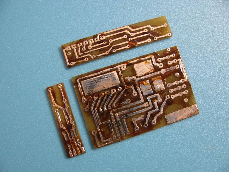
The boards washed with water after etching look like this.
We wash away the toner with acetone or solvent. You can also gasoline or erase stubbornly with the same student eraser.

Then the board is tinned with solder and ordinary pine rosin.
After tinning, we wash the boards in isopropyl alcohol, removing residual rosin.


Then we drill holes on the boards for the installed parts with a drill of the appropriate diameter.
Control board receiver with soldered buttons and a connector for connection.
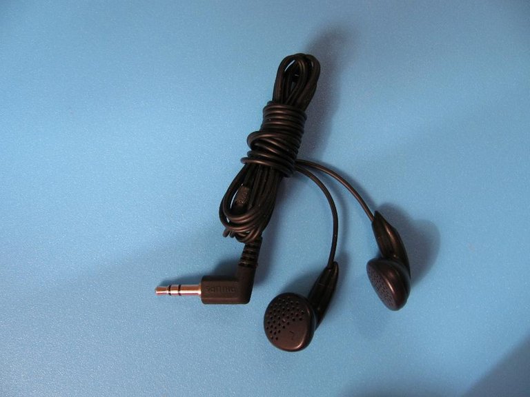
Virtually any wired stereo headphones are suitable for use with the receiver. I use one of the simplest - the Philips SHE1350 model, with a resistance of 20 Ohms. You can buy them, for example, here or here.
They are inexpensive, but they sound, it seems to me, just wonderful.
Clear transparent sound.
You can use your favorite headphones.
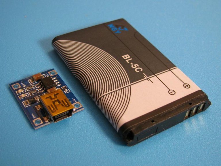
Initially, I used a BL-5C lithium-ion battery to power the radio receiver along with the TP4056 microcircuit module. But later had to make adjustments. Therefore, if you suddenly decide to repeat the construction, do not rush to purchase BL-5C batteries in advance. And better read all the parts of the article to the end.
Everything is ready for soldering the radio receiver board.
Although we drilled holes in the board of the radio for better fastening of the components, we will solder the radio components from the printed conductors side. Thus we win a half to two millimeters in height.
Rectangular cut-out in the lower right corner of the board - the headphone jack will be located in this place in the radio receiver housing.
The green cylindrical two-pin strip element is not a resistor, but an inductance.
Before soldering a module with a microcircuit on its bottom side, you need to glue a piece of plastic insulation tape to the size of the module so that there are no short circuits with the conductors of the printed circuit board.
Soldered.
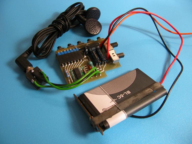
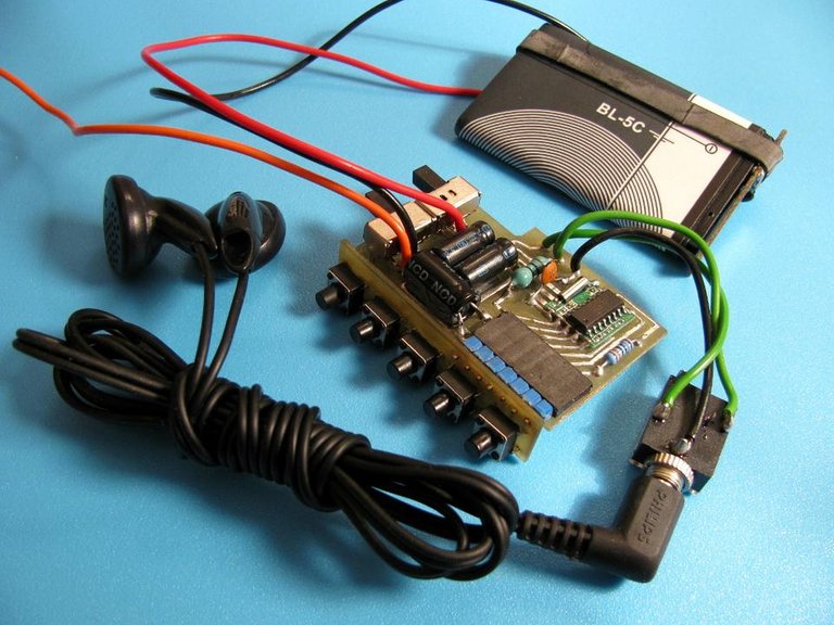
A working test bench looks like this.
You can already listen to "Retro FM" and "Militia wave" and "Radio Romance".
And also "Business FM" to find out the news.
Next time we will add an MP3 player to this design. Do you see that orange wire in the photo with a test stand? This is for him.
Previous posts on this topic:
20.11.2018
Sincerely, Your @mp42b.
Congratulations! This post has been upvoted from the communal account, @minnowsupport, by mp42b from the Minnow Support Project. It's a witness project run by aggroed, ausbitbank, teamsteem, someguy123, neoxian, followbtcnews, and netuoso. The goal is to help Steemit grow by supporting Minnows. Please find us at the Peace, Abundance, and Liberty Network (PALnet) Discord Channel. It's a completely public and open space to all members of the Steemit community who voluntarily choose to be there.
If you would like to delegate to the Minnow Support Project you can do so by clicking on the following links: 50SP, 100SP, 250SP, 500SP, 1000SP, 5000SP.
Be sure to leave at least 50SP undelegated on your account.
@djimirji up!
This post has received a 1.56 % upvote from @drotto thanks to: @mp42b.