Chapter 4 Discussion
4.1 Introduction
In the discussion, a simulation of ICT modeling and configuration was carried out at the Office of Communications and Information Technology, Badung Regency Government with the Cisco Packet Tracer program. A simulation was conducted because the ICT configuration in the Badung Regency Government was fixed and not allowed to be reconfigured or further configured. Therefore, the configuration stage is simulated in the Cisco Packet Tracer program, this program is used because the tool used is Cisco. The ICT configuration in the simulation is exactly the same as the ICT configuration in the field. There are only differences in the model of the tool as described in Chapter 1 section 1.5 Scope and Boundaries, and differences in interfaces.
In Section 4.2 Modem Setup is a public IP modeling where only certain IP addresses can be connected. In Section 4.3 Network Configuration Towards the Internet is the ICT configuration stage from Cisco Multilayer Switches to Modems. In section 4.4 NAT configuration is a configuration for converting local IP addresses to public IP addresses. In Section 4.5, Local Network Configuration is the configuration of Cisco Multilayer Switches to Cisco Switches in each Building. Section 4.6 Connection Test is a connection test using the ping application.
4.2 Modem Setup
The discussion of network configuration will be explained at the same time in the Cisco Packet Tracer simulation. First make a network topology. Starting from the modem configured IP address on the modem (although the modem is not a Cisco device, but its configuration is made close to its original function). According to table 3.5, the IP address at the entrance to the modem is 202.46.10.129/24. Routing used by all routers is RIP (Routing Information Protocol) version 2. The spanning-tree has been configured automatically, namely PVST.
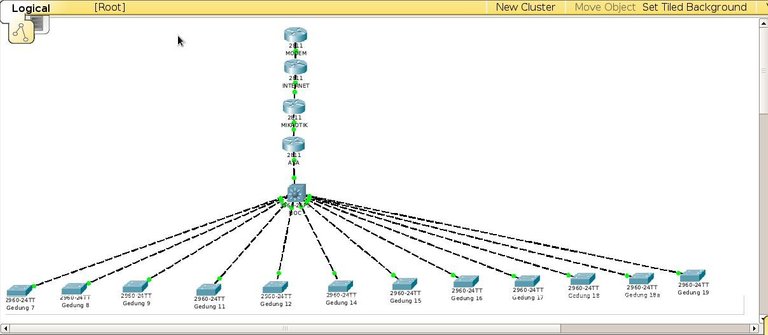
Figure 4.1 Network Topology
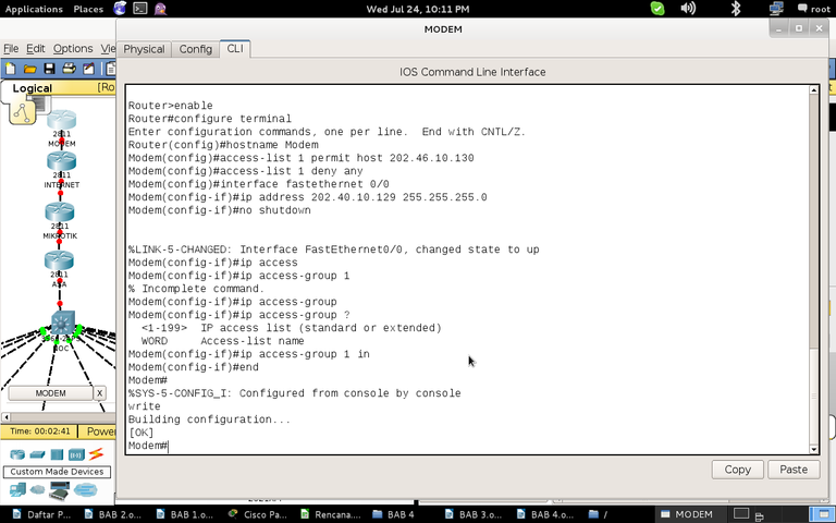
Figure 4.2 Configuring the Modem
- To enter the router you need the "enable" command.
- Begin configuring the IP address on the interface by entering "configure terminal".
- Command "hostname Modem" to give a name.
- The command “access-list 1 permit 202.46.10.130” plus “access-list 1 deny any” so that it resembles the state of the field is configured so that only IP addresses 202.46.10.130/24 can enter.
- To configure an interface, first enter the interface with the command "interface fastEthernet 0/0" (interface fastEthernet 0/0 is the interface connected to the Internet router in this simulation).
- Give an IP address with the command "ip address 202.46.10.129 255.255.255.0", the command "ip access-group 1" to enforce access-list 1.
- To start the interface with the command "no shutdown".
- Finally, the command "end" to exit the configuration and command "write" to save the configuration.
4.3 Network Configuration Towards the Internet
Next, configure the Internet router. According to table 3.5, the Internet interface to the modem with the IP address is 202.46.10.130/24 (in the fastethernet interface simulation 0/1), while the interface from the Internet to Mikrotik has an IP address of 192.168.253.2/24 (in the fastethernet interface simulation 0/0). The configuration method is the same as giving an IP address to the modem, but does not do an "access-list".
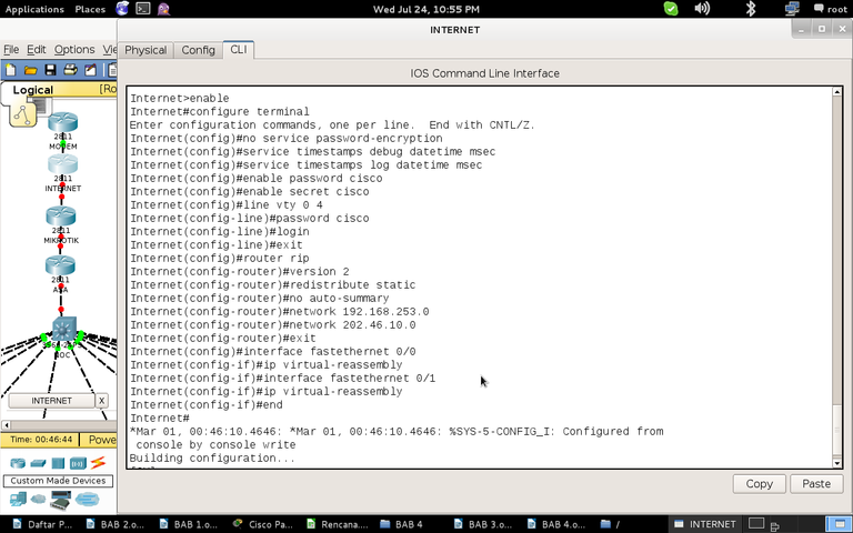
Figure 4.3 Configuring an Internet Router
- In addition to this configuration, the "no service password-encryption" command removes password encryption. The commands "service timestamps debug datetime msec" and "service timestamps log datetime msec" to record every time a configuration change occurs.
- The "enable cisco password" and "enable cisco secret" commands give the "cisco" and "cisco" secret "passwords where required for telnet login. The command "line vty 0 4" followed by "cisco password" and "login" to activate the telnet server with the password "cisco".
- "Exit" to exit a configuration. For routing, RIP version 2 is used where version 2 supports classless routing (not limited to classes A, B, or C) while version 1 can only route class, for example the 192.168.10.0 network reads immediately 192.168.10.0/24 even though what you want is 192.168.10.0/ 26 or other. "Redistribute static" means passing a static route when a static route is configured. "No auto-summary" to not activate auto-summary, which functions as class routing, which reads the IP address, whether it belongs to class A, B, or C, auto-summary can only be turned off in RIP version 2, and cannot be in version 1. Command "network 192.168.253.0" to add neighboring network information. According to Stallings regarding RIP in Chapter 2, each router will exchange information with neighboring routers in order to choose a path. The order is an order to introduce the neighbor. RIPv2 is not done on the 202.46.10.0/24 network because it is assumed to be a modem.
- Therefore, a static route is added to the Internet with the command "ip route 0.0.0.0 0.0.0.0 202.46.10.129".
- Each interface adds an "ip virtual-reassembly" to prevent attacks that take up the time and memory needed to compile packets of data.
- Overall, this router configuration is similar to the Cisco Router 2900 configuration. The configuration method is the configuration in Figure 4.2 plus the configuration of Figure 4.3 based on table data 3.5.
This report does not discuss the proxy configuration, therefore in this simulation how to configure a router called Mikrotik is the same as a router configuration called Internet. According to table 3.5 the interface to the Internet (fastEthernet 0/1) is assigned the IP address 192.168.253.1/24. In a connection, for example, between the Internet and Mikrotik interfaces must be on the same network ID. 192.168.253.1/24 (from Mikrotik) and 192.168.253.2/24 (from the Internet), according to Sutanta in theory, the IP address in Chapter 2 is on the same network ID, namely 192.168.253.0/24. The interface to ASA has the IP address 192.168.101.2/24. RIPv2 is "network 192.168.253.0" and "network 192.168.101.0".
Cisco ASA is a device for firewalls. This report does not discuss data security, therefore in this simulation the Cisco ASA configuration method is the same as the Internet Router configuration. According to table 3.5 the interface to Mikrotik has an IP address of 192.168.101.1/24, according to Sutanta 192.168.101.2/24 and 192.168.101.1/24 are on the same network, namely 192.168.101.0/24. The interface to the NOC (Cisco multilayer switch cat4500e in the field) has an IP address of 172.16.128.2/24. RIPv2 is "network 192.168.101.0" and "network 172.16.0.0". "Network 172.16.0.0" is used because according to table 3.4 NOC will have IP networks of 172.16.0.0/24, 172.16.16.10.0/24 - 172.16.35.0/24, and 172.16.128.0/24. Therefore RIPv2 "Network 172.16.0.0" will deal with IP addresses 172.16.0.0 - 172.16.255.255.
How to configure Internet routers in Multilayer Switch NOC (Cisco Multilayer Switch cat4500e in the field). There is a slight difference. By default, all NOC interfaces on the NOC function as switches.
- To give the IP address of the interface to ASA (gigabitethernet 0/1), that is, the switch mode is turned off with the command "no switchport". Then proceed with giving the IP address according to table 3.5 with the command "ip address 172.16.128.1 255.255.255.0" and the command "no shutdown" to turn on.
- RIPv2 is "network 172.16.0.0", only 172.16.0.0 - 172.16.255.255 are connected according to table 3.4.
- Assuming it can go to the Internet network as in the field, a static route is given with the command "ip route 0.0.0.0 0.0.0.0 172.16.128.2", meaning that it goes to all IP addresses of 0.0.0.0 with all subnet masks 0.0.0.0 through 172.16.128.2, namely the IP address interface in ASA is connected to the NOC.
- In this simulation, the command "ip routing" is required to enable routing.
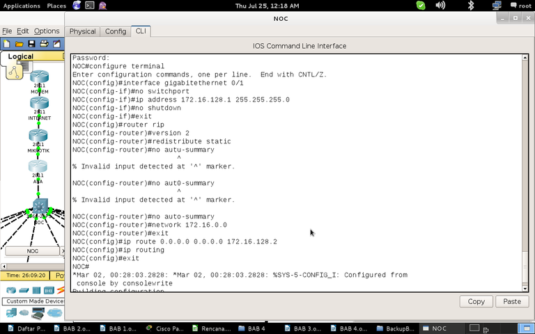
Figure 4.4 Configuring NOC
4.4 Configure NAT (Network Address Translation) on the Cisco Router 2900
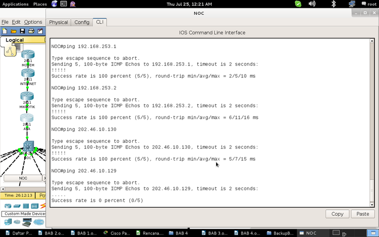
Figure 4.5 Testing connection using PING from NOC
Based on all the above configurations it is not enough to connect from NOC to Modem. NOC to ASA, Mikrotik, and the Internet can be connected but not to the Modem. In fact, only the IP address 202.46.10.130 can be entered in the field.
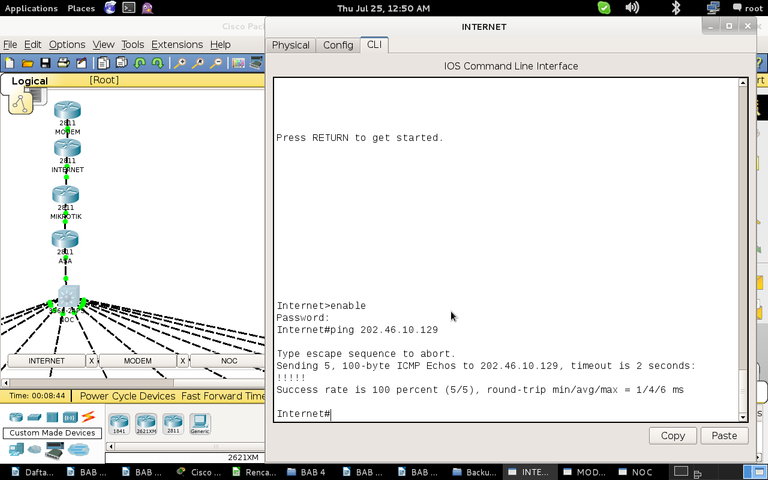
Figure 4.6 Internet router can be connected to a modem
According to table 3.5 there are 2 public IPs, namely on the Internet and Modem. In order to connect to the modem, the incoming IP address must be converted to 202.46.10.130.
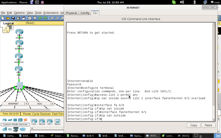
Figure 4.7 Configuring NAT on an Internet Router
- First you have to create an access list that allows everyone to enter with the command "access-list 2 permit any", the name of the access here is access-list 2.
- The command "ip nat inside source list 2 interface fastEthernet 0/1 overload" is a command to perform NAT (Network Address Translation). Ip nat inside converts the incoming IP address from the Internet router, based on access-list 2 (source list 2) is converted to exit via the fastethernet 0/1 interface, that is converted to the IP address assigned to the interface (202.46.10.130), overload command so that all types of incoming IP addresses are converted to 1 IP address.
- After that, it needs to be installed from the data packet entry interface (fastEthernet 0/0) "ip nat inside", and on the data packet exit interface (fastEthernet 0/1) "ip nat outside". The configuration to go to the Internet network (exit the modem) has been completed.
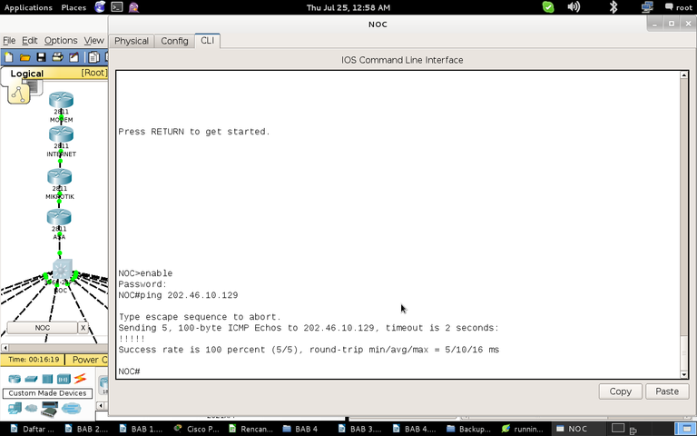
Figure 4.8 Testing connection with PING from NOC to Modem
4.5 Local Network Configuration
The last configuration is on the LAN (Local Area Network), which is the configuration connecting all Cisco c3700e switches in all buildings to the Multilayer Switch cat4500e in building 10 (NOC). Providing VLAN identity per building and per service based on table 3.3. In this configuration, the interface of each VLAN in the NOC is made with an IP address based on table 3.4 and the table provides information on VLAN installation on several interfaces on the switch of each building. For how to configure the switches for each building is the same. So at this writing the local NOC configuration will be displayed and only 2 switch configurations from 2 buildings.
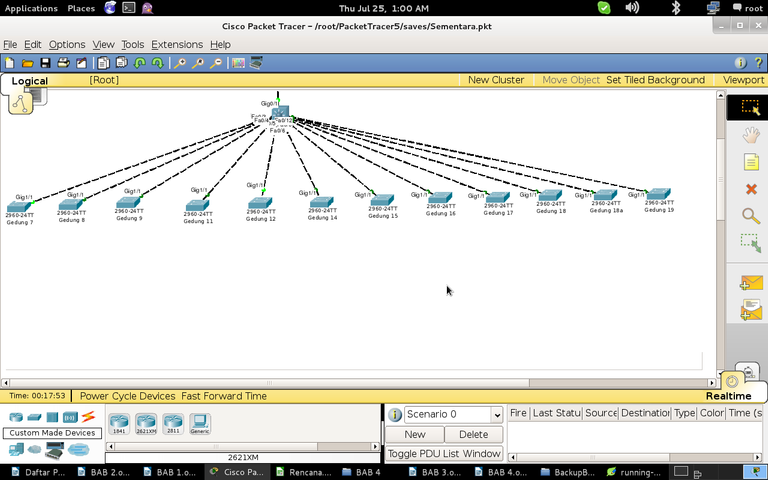
Figure 4.9 Local Network Topology
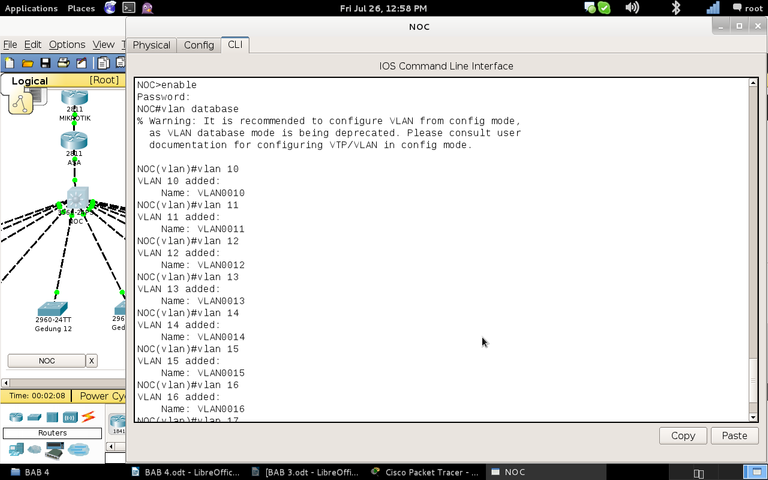
Figure 4.10 Local configuration on NOC 1
Depending on the device, the “VLAN database” command can be configured before the configure terminal or at the configure terminal, this command will enter VLAN settings. After that, enter the command "vlan 10" to add VLAN 10. Adding VLANs is done according to table 3.3 and table 3.4, adding VLAN 10 - VLAN 35.
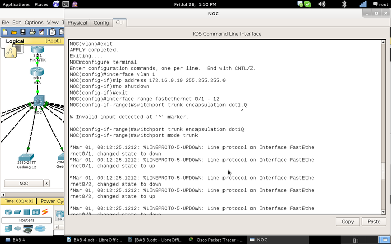
Figure 4.11 Local configuration on NOC 2
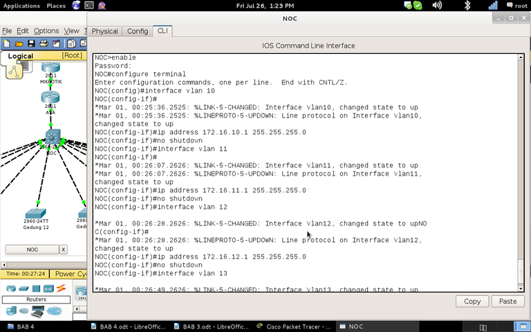
Figure 4.12 Local configuration on NOC 3
Assigning an IP address to the VLAN 1 interface is a way to assign an IP address to a device. According to table 3.3 the IP address on the NOC is 172.16.0.10/24. The command "interface range fastEthernet 0/1 - 12" is a way to enter fastethernet 0/1 - fastethernet 0/12 at once. It was planned on this interface (connected to the switch of each building) so that all VLAN IDs can pass. So the command is "switchport mode trunk", there is a switch that must be given the command "switchport trunk encapsulation dot1Q", which is an IEEE (Intitute Electrical Electronic Engineer) 802.1Q standard, for VLAN standards. According to table 3.4 VLAN interfaces 10-35 are assigned an IP address.
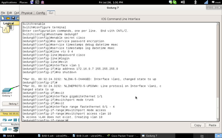
Figure 4.13 Local configuration of Building 7 switches
The initial line is a general configuration performed on all devices, namely, service timestamps, service password-encryption, line vty 0 4 (telnet login), secret installation (MD5 password), installation on the VLAN interface 1. Gigabitethernet 1/1 interface is the interface that connected to the NOC. So that all VLANs can enter, then with the command "switchport mode trunk". Based on table 3.4, the fastethernet 0 / 1-4 interface is given the entry of only VLAN 10 with the commands "interface range fastethernet 0/1 - 4", "switchport mode access", and "switchport access vlan 10". In this simulation, so that VLAN 1 in each building is connected, each switch is given a default-gateway with the command "ip default-gateway 172.16.0.10", which is the default route to VLAN 1 NOC.
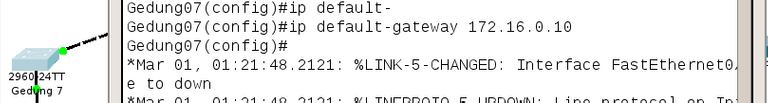
Figure 4.14 Providing default-gateway on Building 7 switches
Next is configuration on the Switch Building 12. The method is the same as Building 7, according to tables 3.3 and 3.4 VLAN 18-20 is installed. For other switch configurations, the method is the same. Then the configuration is complete, to see the configuration results you can type the command "show running-config".
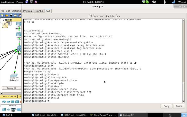
Figure 4.15 Local configuration on Building 12 switch 1
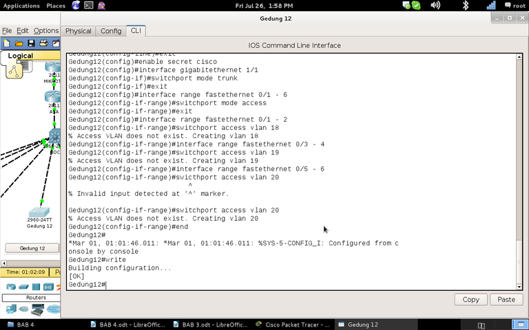
Figure 4.16 Local configuration of Building 12 switch 2
4.6 Testing Connection
At this writing only a few tests were written. First, the computer is installed on the Building 7 switch on the fastethernet0/1 interface. After that configured and ping the interface VLAN 10 and Modem. After that, telnet to the NOC and switch Building 12.
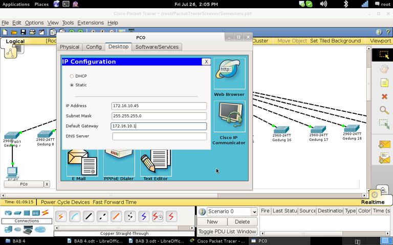
Figure 4.17 IP PC0 Configuration
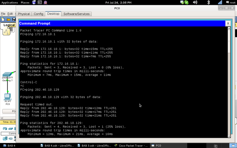
Figure 4.18 PING from PC0 to VLAN 10 and Modem
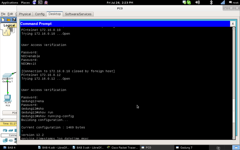
Figure 4.19 Telnet from PC0 to NOC and Building 12 switches
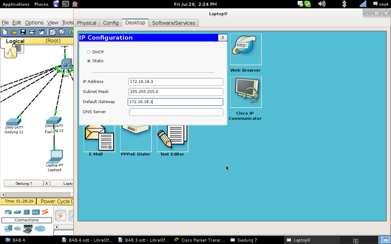
Figure 4.20 Laptop IP Configuration0
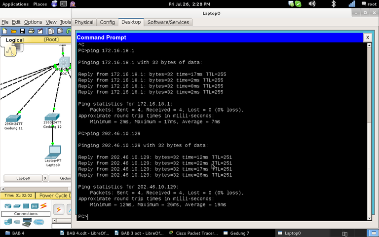
Figure 4.21 PING from Laptop0 to NOC and Modem
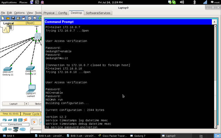
Figure 4.22 Telnet from Laptop0 to Building 7 switch and NOC
Chapter 5 Closing
5.1 Conclusion
The topology on this network is a tree. The local network consists of 12 switches and 1 multilayer switch. All buildings are connected to building 10. Each office is on 1 VLAN ID. The total VLAN used is 25 of VLAN 10 - Vlan 35, with a network ID of 172.16.10.0/24-172.16.35.0/24. Installation of a VLAN ID is carried out in 1 multilayer switch in 10 buildings and 12 switches in all buildings. The port that is connected from 12 switches to a multilayer switch is a trunk mode where all VLAN IDs can enter. Each switch and multilayer switch is assigned an IP address on VLAN 1 as if it were assigned an IP address on the device.
From the multilayer switch to the Internet network must pass through ASA, Mikrotik, Router, and Modem. The multilayer switch port to the Internet network functions as a router so that the switchport mode is turned off and assigned an IP address. After that the routing mode is activated, static routing is used for the Internet network, while for the internal use RIPv2 dynamic routing. Likewise in ASA, Mikrotik, and Router. The router is given 1 public IP. Everything that goes to the router goes to the modem, then to the Internet network, the private IP address is converted into a public IP with NAT.
For the purpose of processing all devices enabled log and debug for notification of changes in the device. Secret and password are activated for telnet purposes. Telnet server is activated so that you can remote login.
5.2 Suggestions
The suggestion that can be given is to improve the quality of the network configuration.
- The first suggestion is to install a point-to-point IP address such as from a multilayer switch to ASA. Network ID 172.16.128.0/24 where there is waste of IP addresses. The IP address used with the subnet mask (255.255.255.0) is 254 IP addresses while 2 IP addresses are required. So it is better if 172.16.128.0/30 is the subnet mask 255.255.255.252. It is recommended for other settings to save IP addresses with a subnet mask.
- The second suggestion is to label each port for a clear description of the port's function.
- The final suggestion is on VLANs. It is easier if the multilayer switch is used as a VTP server, while the other is a VTP client so that the VLAN configuration is sufficient on the multilayer switch. It is better if each VLAN ID is named so that there is information on the device about which VLAN is using.
Bibliography
- Burgess, M. 2004. Principles of Network and System Administration. John Wiley & Sons, Ltd. : Chicester
- Cisco. 2004. Catalyst 4500 Series Switch Cisco IOS Software Configuration Guide. Cisco Systems, Inc : San Jose.
- Gebali, F. 2008. Analysis of Computer and Communication Networks. Springer Science + Business Media : New York
- Inixindo, S. 2005. Workshop Basic Internetworking. Graha Pena : Surabaya
- Peterson, L. Davie, B. 2003. Computer Networks Third Edition. Morgan Kaufmann : San Fancisco
- Stallings, W. 1998. High-Speed Networks TCP/IP and ATM Design Principles. Prentice-Hall, Inc. : New Jersey.
- Sutanta, E. 2005. Komunikasi Data & Jaringan Komputer. Graha Ilmu : Yogyakarta.
- The Internet Center. 2013. http://www.incentre.net/ethernet-wiring-diag.html. Diakses 24 Juli 2013.
- Western Telematic Inc. 2013. http://www.wti.com/p-236-72-3383-01-cisco-rollover-console-cable-blue-db9-to-rj45-6.aspx. Diakses 24 Juli 2013.
Mirror
- https://www.publish0x.com/fajar-purnama-academics/simulation-of-ict-network-configuration-based-on-existing-ne-xllmrrv?a=4oeEw0Yb0B&tid=hive
- https://0fajarpurnama0.github.io/bachelor/2020/11/01/practical-work-report-badung-government-2013
- https://0fajarpurnama0.medium.com/simulation-of-ict-network-configuration-based-on-existing-network-configuration-at-the-network-6de204bab9b9
- https://hicc.cs.kumamoto-u.ac.jp/~fajar/bachelor/laporan-kerja-praktek-puspem-badung-2013
- https://0darkking0.blogspot.com/2020/11/simulation-of-ict-network-configuration.html
- https://0fajarpurnama0.cloudaccess.host/index.php/9-fajar-purnama-academics/90-simulation-of-ict-network-configuration-based-on-existing-network-configuration-at-the-network-operation-center-of-the-badung-regency-government
- http://0fajarpurnama0.weebly.com/blog/simulation-of-ict-network-configuration-based-on-existing-network-configuration-at-the-network-operation-center-of-the-badung-regency-government
- https://0fajarpurnama0.wixsite.com/0fajarpurnama0/post/simulation-of-ict-network-configuration-based-on-existing-network-configuration-at-the-network-opera
- https://read.cash/@FajarPurnama/simulation-of-ict-network-configuration-at-the-network-operation-center-badung-regency-government-8fccc878
- https://www.uptrennd.com/post-detail/simulation-of-ict-network-configuration-based-on-existing-network-configuration-at-the-network-operation-center-of-the-badung-regency-government~Nzk3NjQ2