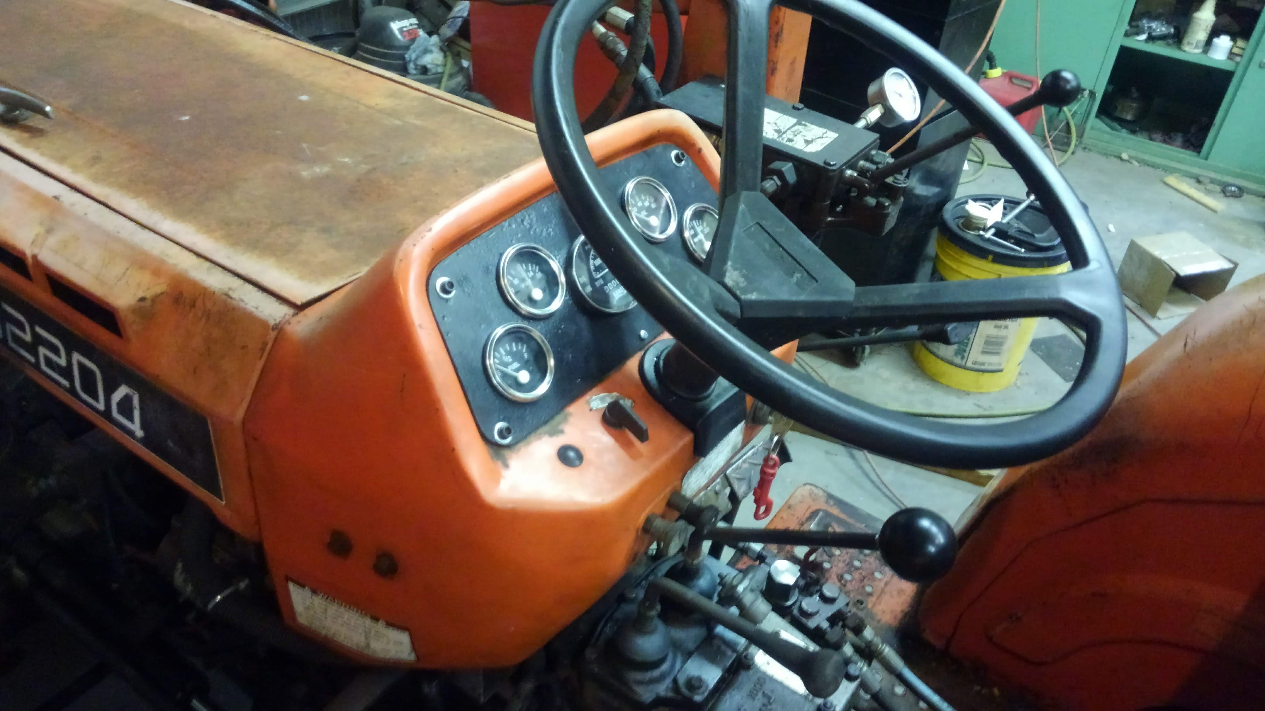
Here's another installment on my Kioti LB2204 tractor. Kioti shipped all of its tractors made up through to the late 1990s with this same dash panel, but for whatever reason they stopped supporting these older products at some point. Pretty much all of these fail and there's no manufacturer solution to get them back working again. Being that the engine needs to operate at or below a specified RPM range to avoid engine damage, and the fact that I have no idea what RPM the engine is spinning at since I bought the tractor, I really need a tachometer. This is not to mention that the hour meter is tied to this mechanism, which is critical to knowing when to do routine maintenance on it.
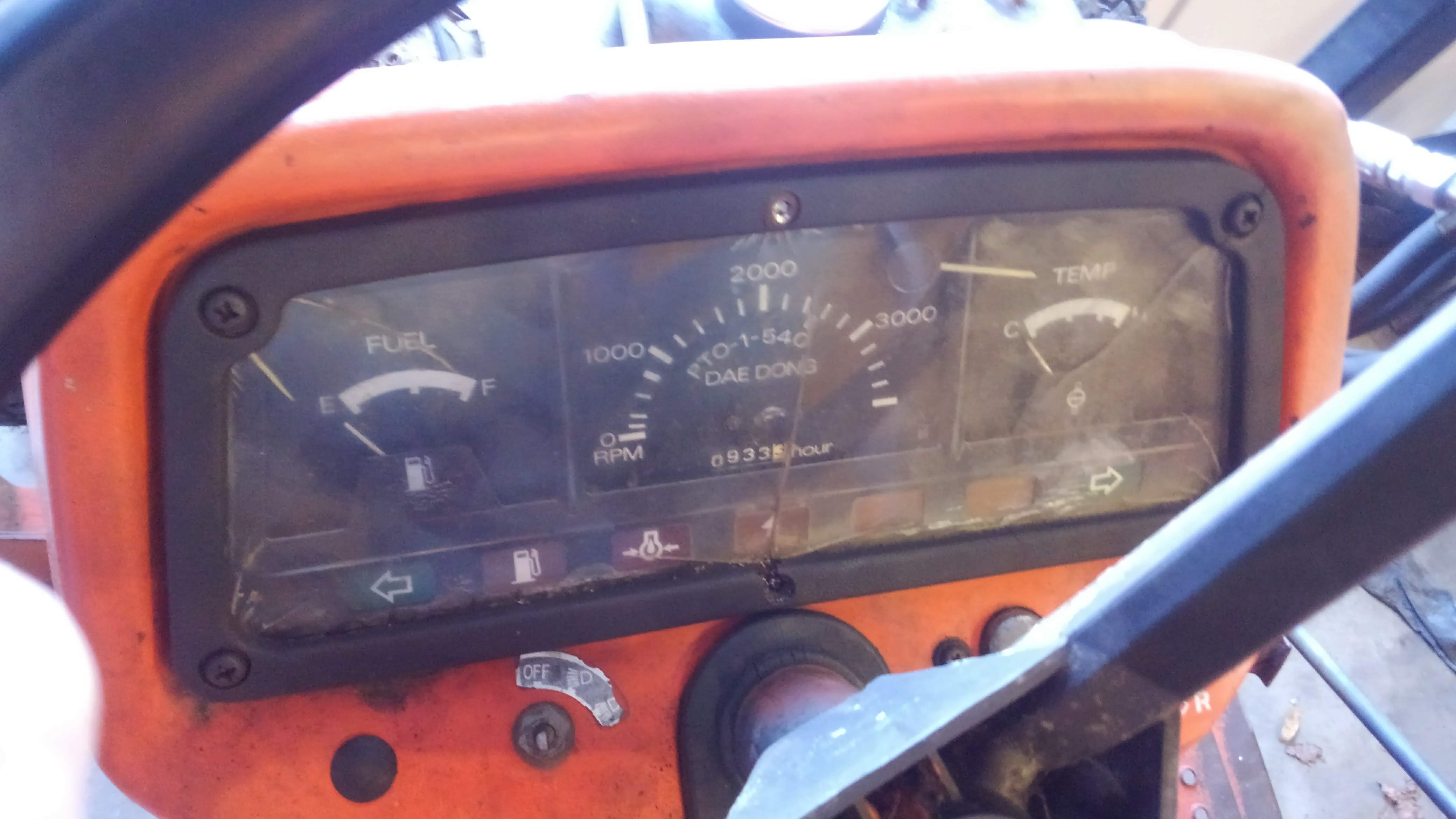
As you can see in the photo, this gauge pod has seen better days. The needle for the tachometer has long since checked out and is floating around in there. The gears inside and the fitting on the back are in similar rig. If I wanted to I could probably get everything in this panel working except of course the tachometer, so there's really no solution except to just replace it with something completely different if it's not the OEM replacement part.
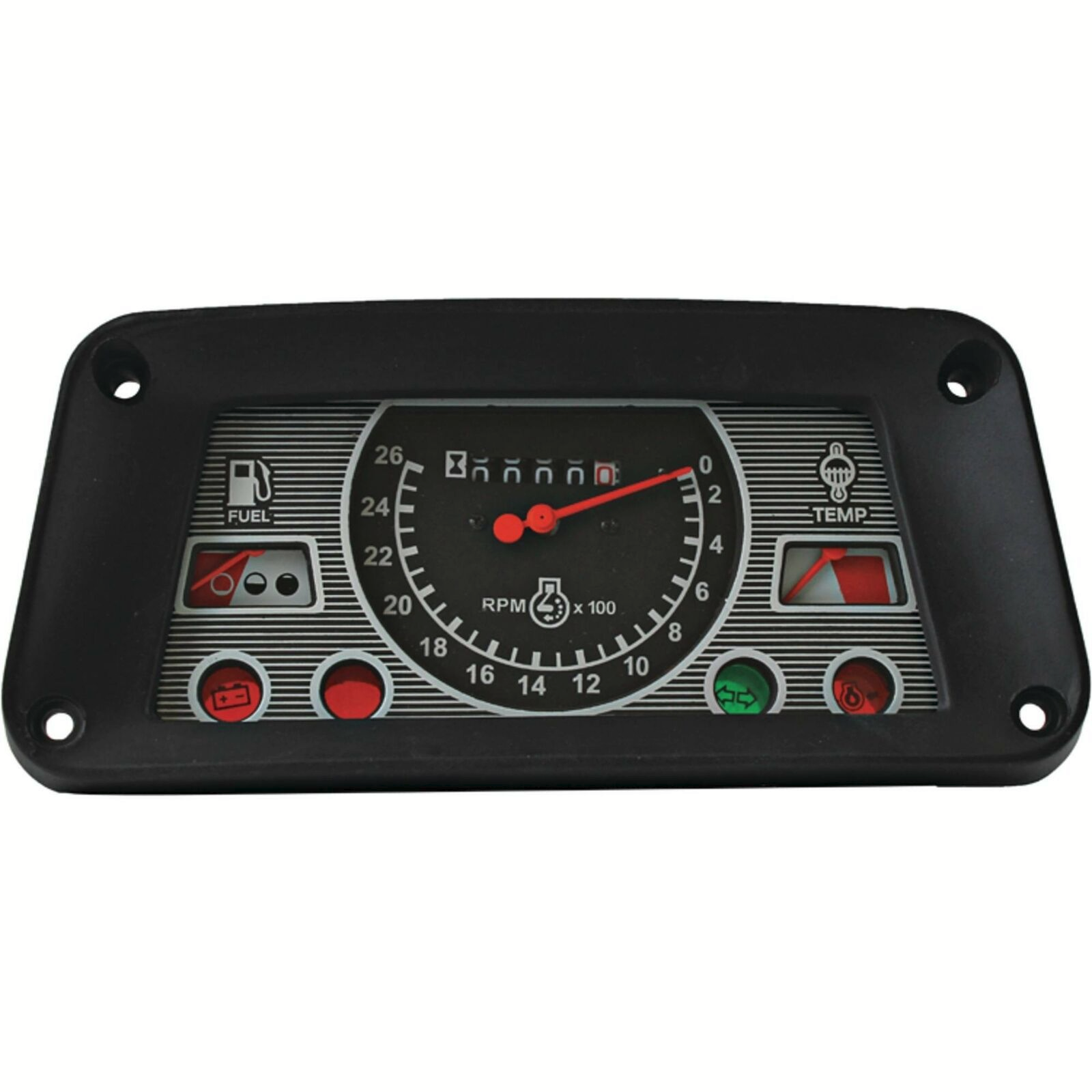
I searched around the forums because I figured with so many of these made, there must be others with this problem who have since fixed it somehow, and sure enough I found a guy who had replaced hist with this "universal" one made to fit an old Ford tractor. It does sort of get the job done, but there are several problems I see with it. First, the tachometer only goes to 2600 RPM, and the engine in my tractor is rated to run at 2900 RPM for full load operating. There's also no guarantee that the gear reduction is calibrated the same way as the Kioti part. While it does sort of fit inside the dash panel and looks similar to the factory part, it's also missing an actual oil pressure gauge (just the "idiot light") and a temperature gauge with numbered graduations so I know the actual temperature rather than just white or red, whatever that means. "Alarmingly hot!" and "Somewhere below alarmingly hot!" is all you get here, and honestly with it being smaller than the original gauge pod, it looked kind of goofy in there with the gap all the way around. I won't post a picture of it so as not to single the guy out. At the end of the day it got the job done for him to his satisfaction, I just decided to go a different route.
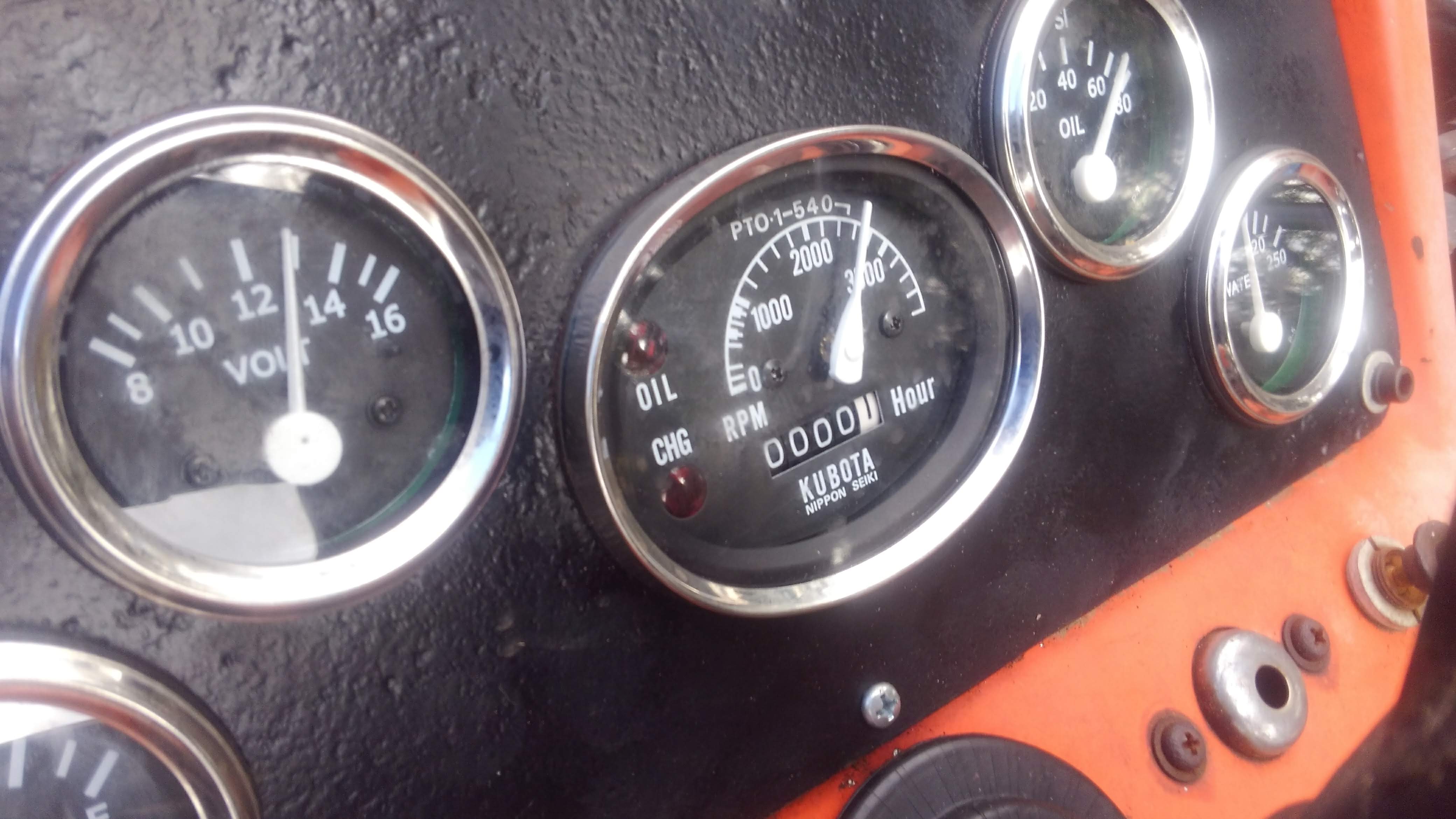
Falling back on my knowledge that this tractor shares many parts with the Kubota L245, I looked up the parts for the tachometer. The part numbers were different between the two tractors, but the drive gear on the engine looked identical, and the threads and driven ends for the back of the gauge and output of the drive gear were the same to accept the cable on both. Having the same engine, the L245's odometer was of the proper RPM range for this tractor and it was likely calibrated the same via the gear ratios.
Here's me getting sophisticated with what I like to call pizza box CAD, or Cardboard Aided Drawing. This is for transfer of the dimensions over to a piece of steel plate I'll use as the blank to accept the gauges and make my dash panel out of. I could just go straight to the piece of metal, but as they say, measure twice, cut once. In this case make a cardboard template and if you screw something up, you're out only a piece of cardboard. Test fitting this on the tractor yielded good results so I transferred a line directly from the cardboard to the metal for it to be cut out with a cutoff wheel on the angle grinder.
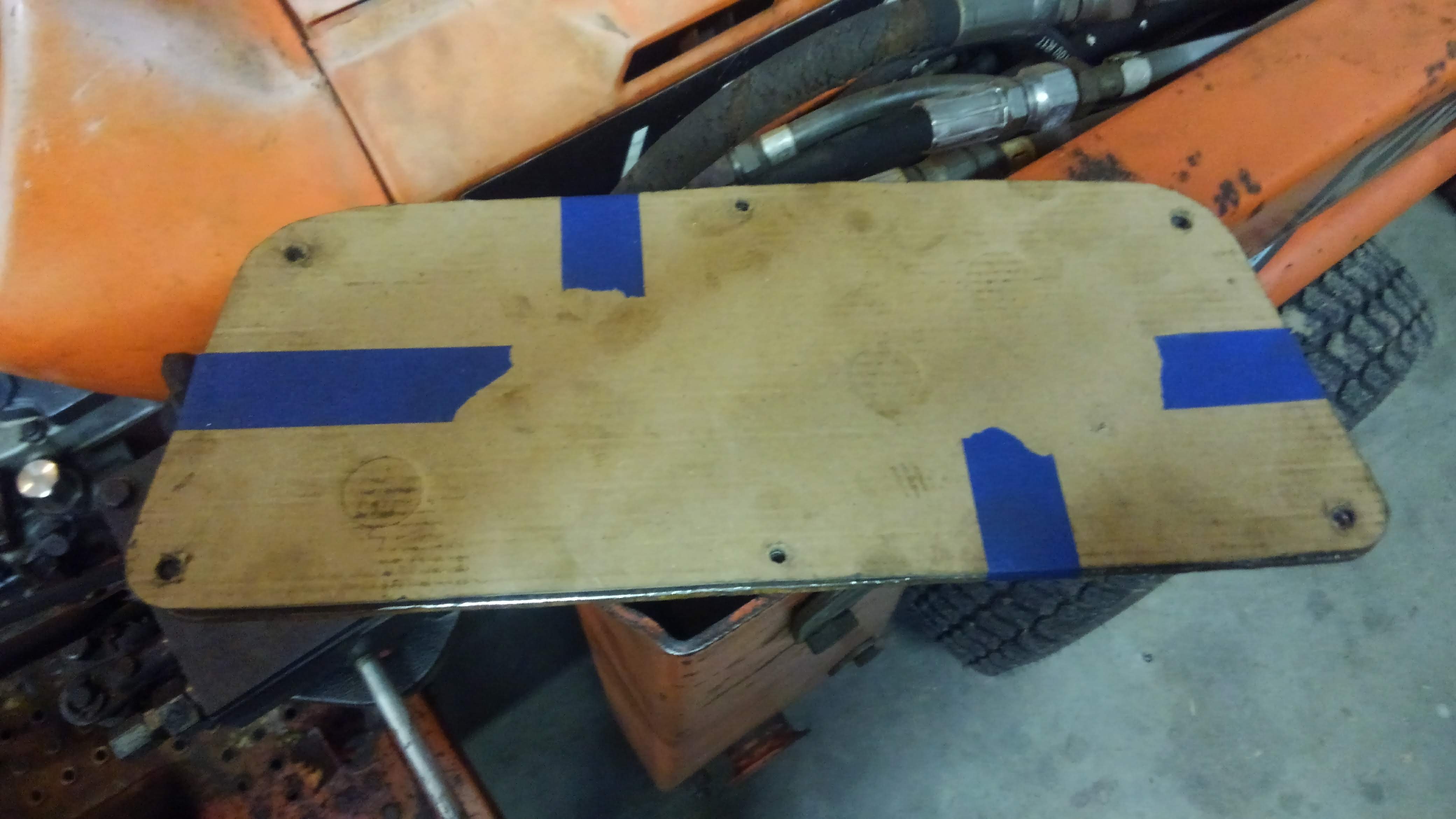
Same idea here. I transferred the screw holes to the cardboard first, then taped it to the piece I cut out so that the holes could just be located visually that way. They ended up still being a little bit off. On one of the holes the drill bit skated off to the side a little because of the rust pitting, but I just made the holes a little bit bigger and they fit fine after that.
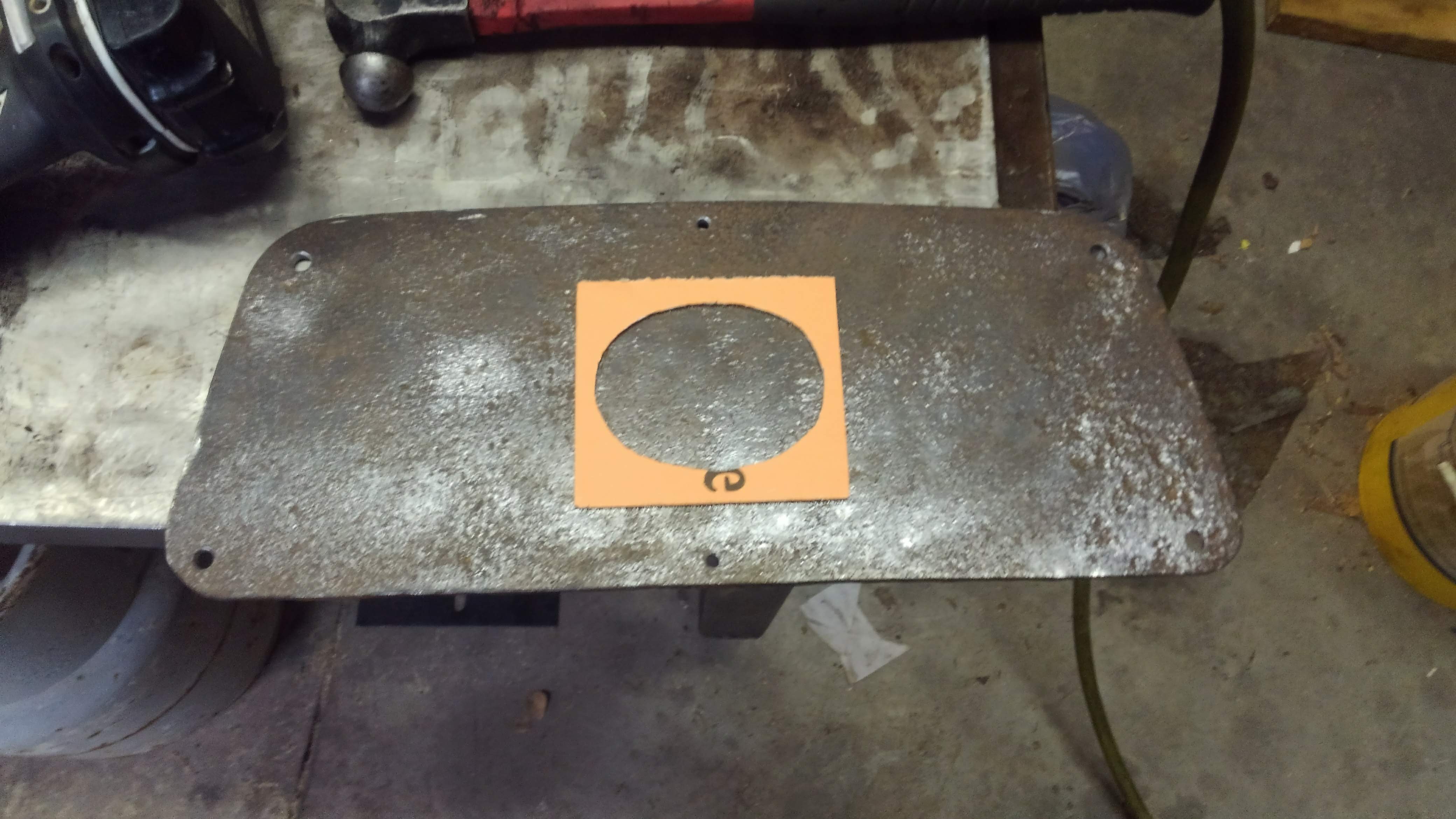
This is the template used for the gauge. Same idea. This made it a lot easier to locate the unusual shape of this gauge so that it visually looked centered. I didn't measure here since the piece I'm cutting into isn't a precisely made part. Eyeballing it will have to be good enough.
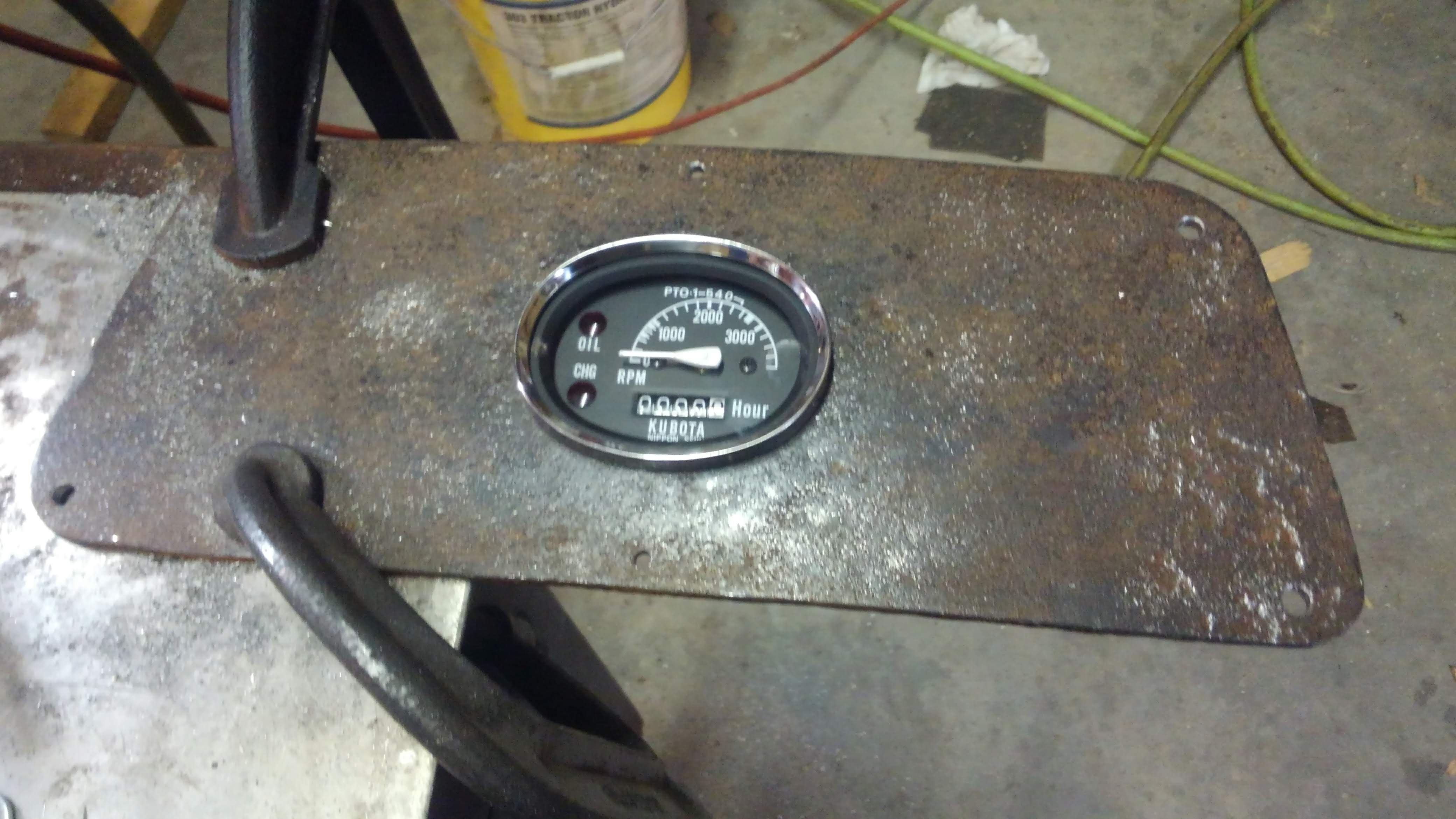
The location turned out good I think. With the dial of the gauge being off center, it's hard to visually tell if I have this properly centered, but if you cover up the dial, it looks pretty close to perfect. This was cut out using a jig saw with a metal cutting blade. Because the piece I used was 3/16" plate steel, it ended up taking a very long time to cut it. Once it was cut, the size was a little small, so I went in with a carbide burr on the die grinder to take off just enough material to get the perfect fit.
.jpg)
Here's the part where improvements are made on the factory setup. I bought a set of 2-inch gauges off of eBay. These were laid out visually as well. As you can see I drew a line on the outside to tell where the edges of the sheet metal I'm screwing this to would land. This gave me a reference to just plop the gauges upside down and get a rough location for them. I then took another piece of carboard and drew a circle on it the size of the hole with a compass, making sure to leave a large impression in the center. I then cut it out with a pair of scissors as precisely as I could, then opened up the center hole with a punch to just big enough to accept the tip of my marker. This allowed me to both visually locate the hole's external diameter on the plate and also accurately locate its center. Once all of these were located where I was happy with them, it was just a simple matter of center punching each where the center mark was and then drilling with my hole saw on the mill. This could be done on a drill press too, or even by hand if you're careful. If I had it to do over again, I would not have been so cheap and would have instead bought a piece of plate aluminum to make this out of. The old rusty steel was such a bear to work with.
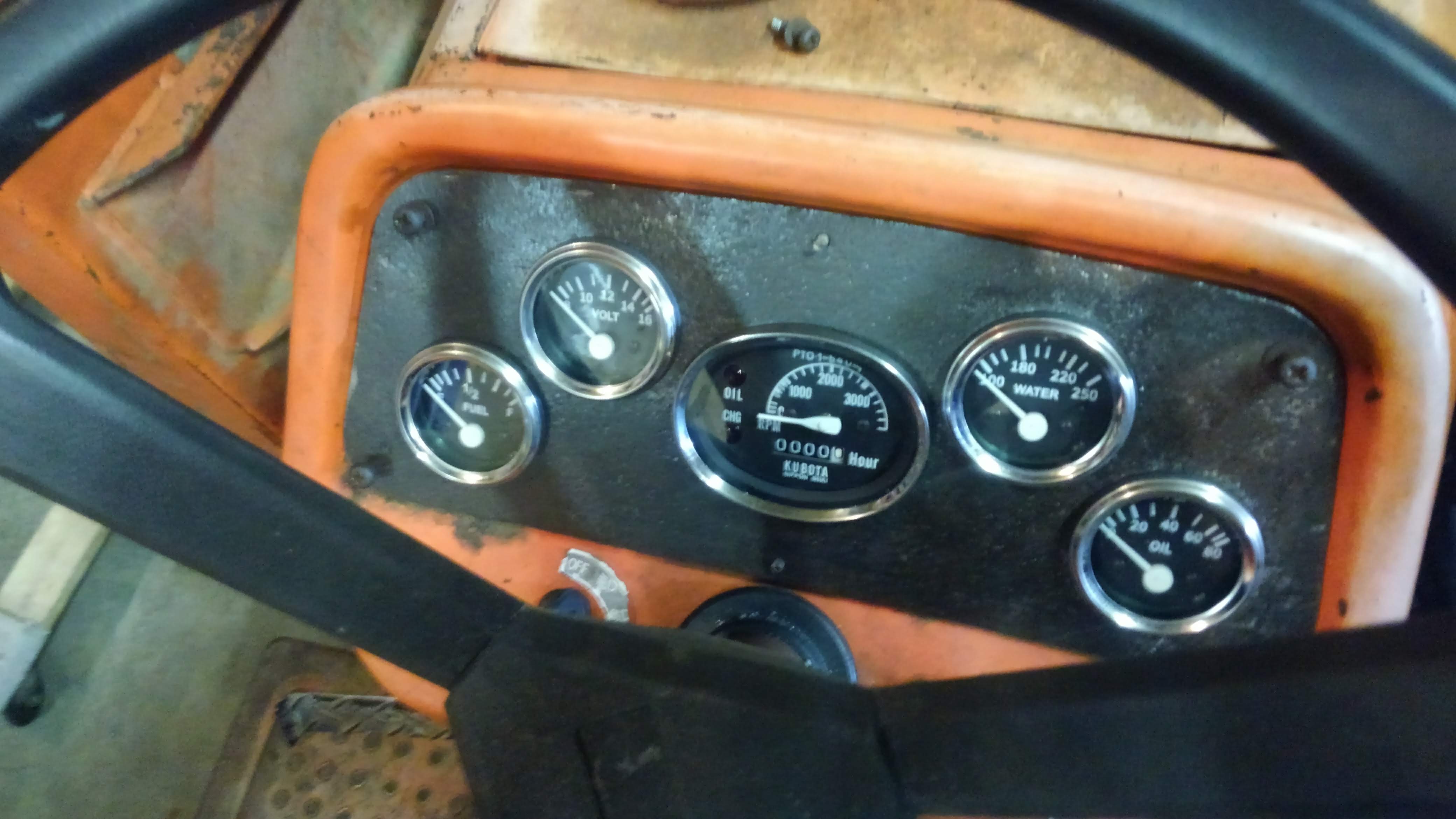
This is the first test fit. Looks great right? Indeed, but the job is only about half done here. Now for the tedious task of wiring all of these in and hooking up the tachometer.
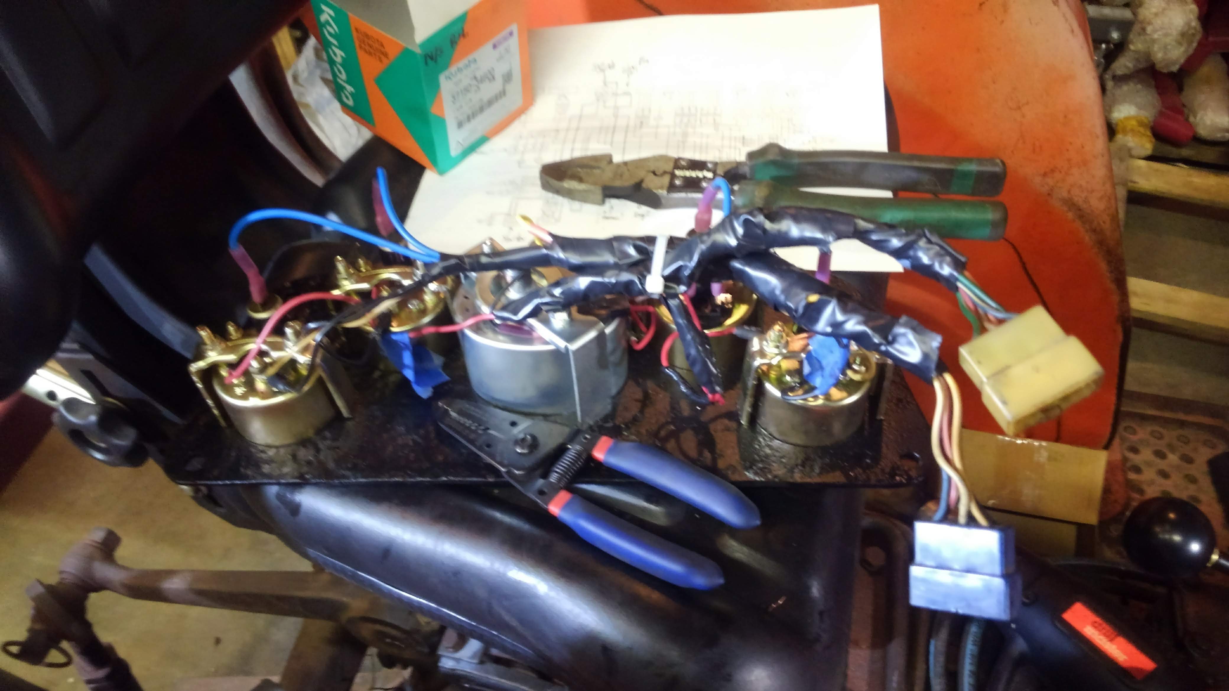
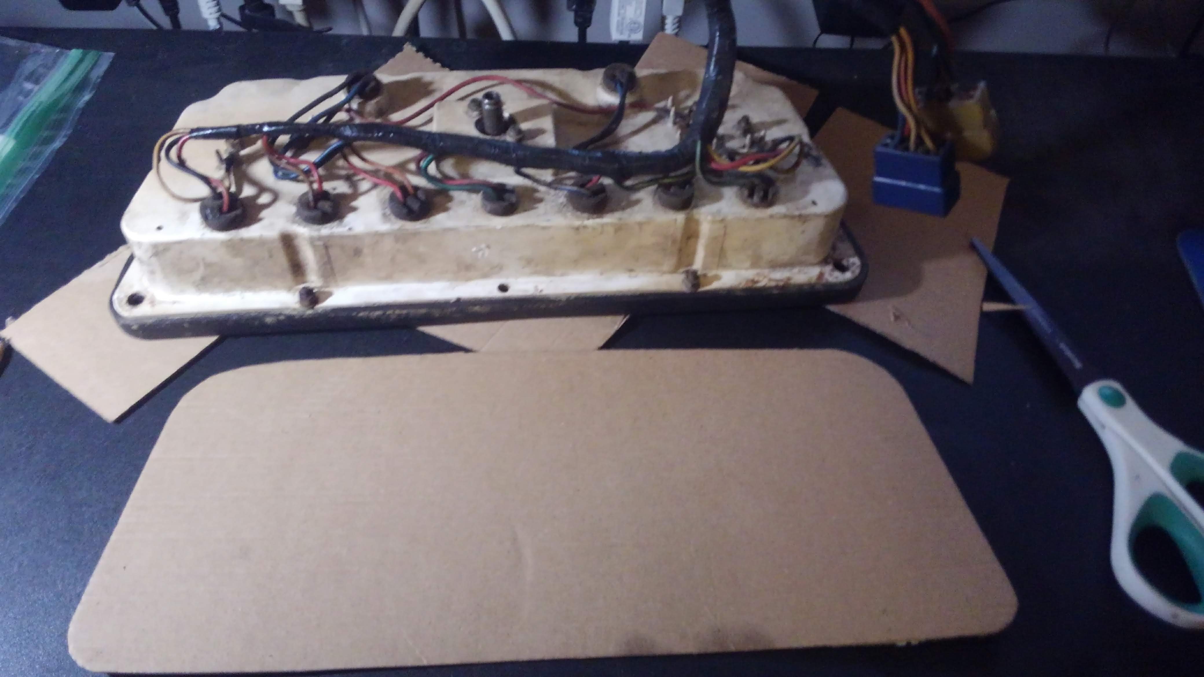
I won't bore you with all the detail on the wiring, but this is roughly what I came up with. I used as much of the existing harness as I could. This ended up being almost a full day of tracing and labeling wires, cutting, stripping crimping and heat shrinking everything together to get it into a neat little package that would end up lasting a long time. I only had to run one separate wire, and that was for the oil pressure sending unit. The OEM location where the pressure switch is screwed into the side of the block is too tight to fit the large sending unit I purchased. Doing it this way with the factory pigtails has several advantages. The plugs from the factory setup were retained so if I need to service something under the dash, this can simply be unplugged and removed to make room. All of the wiring for all of these gauges was pretty much already there, so I didn't have to run any new wiring except for that one. These already have fusible links in place so there's no need to add ones like I did with the alternator charging wire. I was even able to retain the backlights for the gauges when the headlight switch is turned on. I don't have any headlights yet, but it's good to know I'll be able to see my gauges in the dark if and when I do get some functional lighting installed back on this machine. Finally, it ended up going a lot faster than it would have. Ask anyone who has wired something like this up from scratch. For as long as it took me to do this job, it would've taken probably three times as long to get a whole new harness built, and it would've been expensive too. Copper is not cheap these days. Because I had everything else as far as connectors and lengths of wire in house to build out this harness, it cost me free ninety nine to get this part done.
I did run into several problems while putting this together. Some of the OEM wiring that I retained had really thin shrink wrap on the connector ends, and it basically disintegrated while I was handling it. This resulted in a dead short onto the body of one of the gauges that caused it to keep popping fuses. Lucky for me those were there and I didn't melt down all the work I had just done when I turned it on. Easy fix, but frustrating to track down. I also ran into several problems with the tachometer. First, the cable, which tested good when I last had it apart, decided that it wanted to exit stage left when I went to use it. It broke immediately upon having the slightest of load. That took a few days to get in, then when I hooked it up, the next weakest link failed, the drive gear that runs off the engine. Again, that took a few more days and it was very expensive. I actually ended up finding a seller that sold an entire gauge, cable and drive gear for another Kubota machine that I was able to buy for cheaper than just the drive gear by itself. I'll probably end up just putting those other parts back up on eBay and flipping them.
So here it is in all its glory, giving me all the data I have been craving since I rebuilt the motor. The oil pressure and RPM being the most important to me. I found out that it's got great oil pressure. I knew it had some kind of oil pressure before because it was getting oil up top and there was no rod knock, but I had no idea what it was beyond say 10 psi minimum. I figured it would be good, but given the fact it still has the original oil pump in there, I'm impressed that it's so high. It sits at about 65 psi when it's at full song, which is the top part of the spec'd range for this engine, so as good as it gets. I also found out that this engine gets a little more frisky than it should because it will rev well north of 3000 RPM even though it's rated for 2900 at peak power. This is exactly why I was concerned about this data point, because these little diesels, even though they will rev all day every day at that max power RPM, they will float valves if you go much higher than that, which would be really bad. Valves contact pistons, keepers fly off, valves drop into combustion chambers, and boom. We don't want that. So now I'll just keep it under 3 grand manually for now until I get that sorted. I kind of like that it will give me more fuel than it's supposed to have because it'll give me a little bit more power when it's under a heavy load if I need it, but I probably should fix it sooner than later. I'm living in the danger zone a bit with it like that honestly.
So that's it. Another completed project. Next on the list will be lights or maybe repairing the bucket, but before then I've got a few more posts I'd like to do on this about various other things I ended up fixing on this machine. It's been quite the journey. I'm kind of digging the mad max look this thing is rocking right now. The patina with the flat black accents looks almost like I did it that way on purpose, so I might just go with it. What do you guys think? Should I shine this tractor up with fresh orange paint or put some shine juice on the rust Vice Grip Garage style and keep going with the rusty patina and clean flat black accents?
Pretty awesome job. I like the patina myself, but you don't want to see my truck. You done great. Inspirational.
Thanks!
Thank you!
The rewards earned on this comment will go directly to the person sharing the post on Twitter as long as they are registered with @poshtoken. Sign up at https://hiveposh.com.