.jpg)
SCHEMATICS READING
Hey guys welcome to another blog post. So sometime ago when i started learning ,when i was given a schematic diagram of a 555 timer in astable mode, i was shown something that looked like a terrible representation of the 555 timer ic connection. I mean it was literally confusing and when i tried to "build" by "following the lines" of the schematic, i failed horribly.
So today i want us to address the very important issue of the schematic diagram
reading
What is a schematic diagram?
Before we begin this journey i want us to be clear on what we are talking about so that we are the same page.
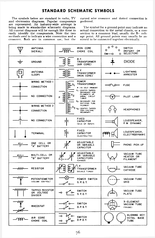
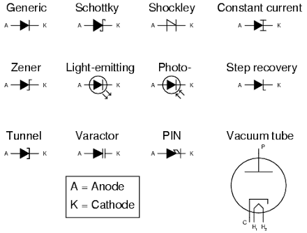
A schematic diagram is defined as maps that provide guidance on the functioning, assembly and service of an electronic circuit. Simply put they help us with a overlook on how a given circuit connection was made more like a blueprint. Now the first thing to note about schematic diagrams is that they consists of symbols and lines. So therefore i would highly recommend that u have a very basic understanding of the common symbols used in electronics and to help you do that i would recommend that you go through the diagram or picture below actually the 3 pictures below.
Source: google images
.jpg)
.png)
Let me say it again you need to get familiar with these common symbols used in electronics and yeah you need to study these.
STEP INVOLVED IN SCHEMATIC READING
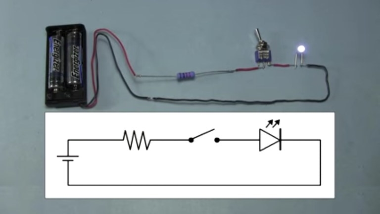
Lets begin with the schematic above. It is very simple circuit which is basically used to light up an led.
Step 1
Identification of the components that are being used is the first thing we have to do . We see that they include:
*battery or a cell
*an led
*an on off switch
*lines that represent wire connections
Step 2:
Knowing the components involved in the circuit we move to knowing the movement of the diagram i.e. locating where the connection starts and is terminated for each component for example the led connection starts from the resistor and ends at the negative of the battery note that for a battery representation the longer part is positive and the shorter part is negative.
Step 3:
Actually knowing how the components work and their function in the given diagram is the third and final step in understanding schematic diagrams. knowing how they connect without actually having a clue as to how they work would still lead you to be more confused than ever and this is where a bit of experience comes in. And don't worry i am gonna be doing a series on common components that are used in electronics. There we would brush up on this issue. That's a bit steeping out of line so why don't we get back to the original thing that brought us here in the first place.
In the circuitry above the switch acts to turn on and off the circuit, the resistor is used to protect the led by limiting the amount of current entering it and the battery is used to provide the source voltage
Essentially it is that easy so lets run through this again. To read a circuit diagram we need to do the following:
*identification of parts used in the circuit
*knowing the direction of the circuit
*knowing the function of key components in the circuits
These are some of the basic steps involved in reading electronic schematics. I am also interested to know if you have any suggestions and ideas that you would like to share on how to read schematics please leave them in the comments below
Also don't forget to give this an upvote, resteem and comment. Thanks for spending time here and for that let me leave you with a bonus schematic diagram, that you can go and try
.jpg)
Always label the source of all the images used in your article appropriately and use copyright-free images. Thank you.