If you've ever wondered what's inside the LED light bulbs that screw into the socket, you've come to the right place. I'll be showing you what is inside this cheapest of the cheap LED light bulb, and how it works. Unfortunately this short teardown resulted in the death of said light bulb, but I suppose it's reasonable to make getting into high voltage stuff slightly difficult.
LED light bulbs are typically the most energy efficient light bulbs, compared to florescent bulbs (ionized tubes of gas) and legacy incandescents (filaments heated up to glow red-hot). They also power on immediately (unlike florescent tubes) and use very low amounts of power. This makes LED light bulbs better for your power bill and for the environment. Let's see what's inside one.
Breaking Into a Light Bulb
This light bulb was obtaining a while ago at my local dollar store in order to test some 120VAC inverters I had. The bulb screws into your ceiling, and converts 120VAC from the wall into visible, white light. It's a simple looking device, and is apparently rated for 7 watts:
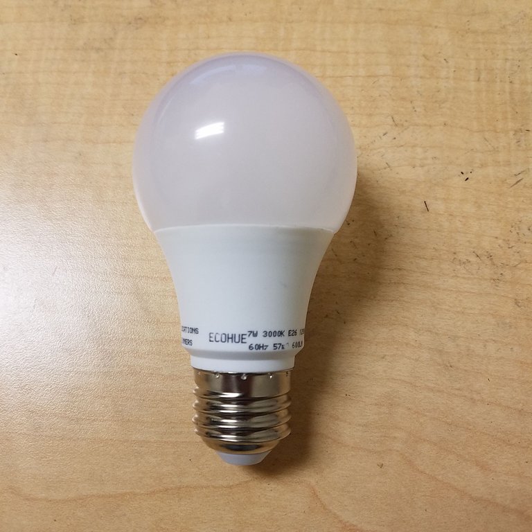
Plug it in and it lights up, simple as that. Unfortunately there are no screws to make access easy, but this is to be expected since it's a wall voltage device. I found a simple way to get in, but it required destroying the bulb: Placing a thin flathead screwdriver or knife under the seam between the opaque bulb and the base can quickly remove the bulb itself.
The plastic bulb serves the task of diffusing the bright LED light. If this bulb wasn't here, looking directly at the light would be quite painful as the tiny, intensely bright LEDs would go straight to your eye. Electrically it serves no purpose.
Inside, the circuit is visible:
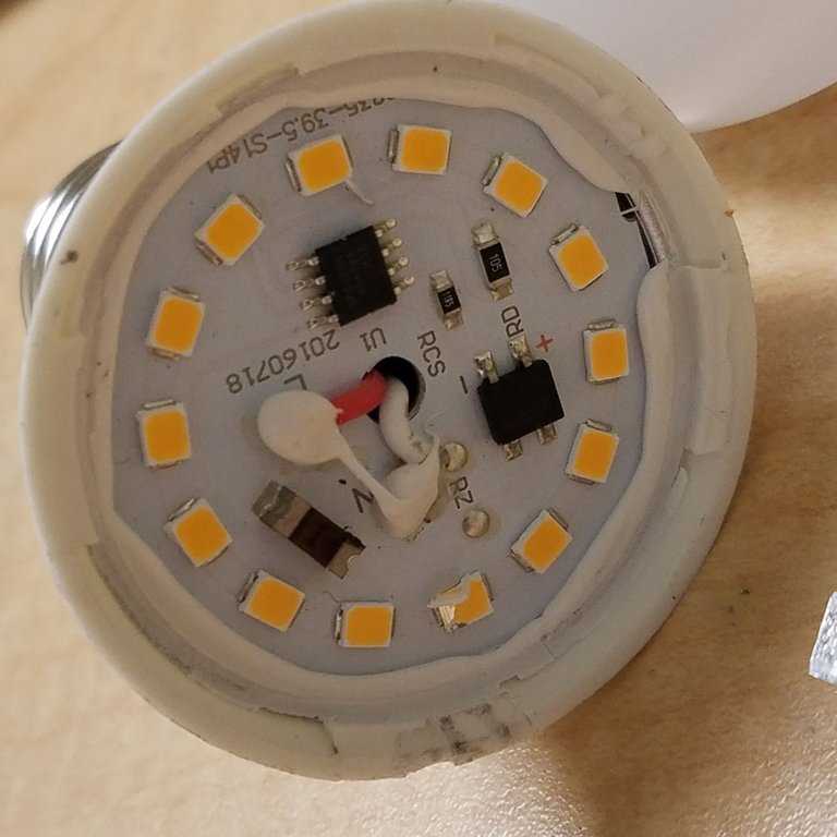
14 yellow colored LEDs encircle two surface mount resistors, two semiconductor devices, and a red surface-mount fuse labelled "I" for current (this fuse just prevents the device from causing trouble if something were to short, and will break if it exceeds its rated current).
Sometimes these bulbs have capacitors and other components hidden under the PCB (the more interesting florescent tube circuits also obtainable at the dollar store have a ton of components hidden here), so I tried to pry off the circuit board from the enclosure. After failing to do so for a few minutes, and damaging a few of the LEDs, I used a pair of pliers to physically destroy the sides of the plastic enclosure. This lets the board fall out to reveal .. nothing. The only components behind the PCB are a pair of wires, leading from the screw terminals (that connect to the wall) to the light PCB. This means that everything to run this circuit is contained in the slim number of components visible above.
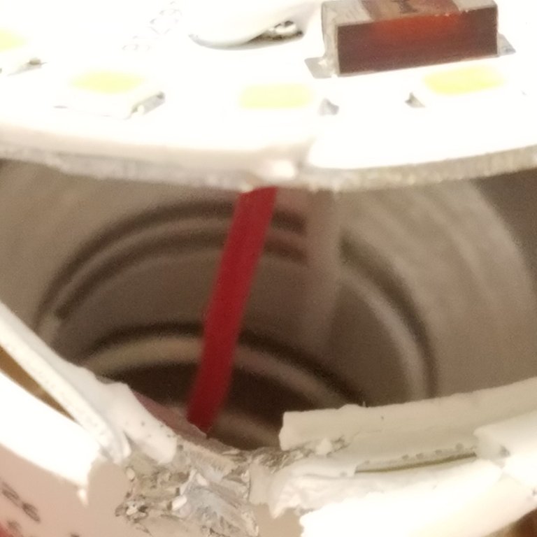
The disappointing underside. The inner chamber is surrounded in what looks like aluminum metal, and is likely used as a heat sink for the power hungry LEDs
Let's take a closer look at the integrated circuits on board the PCB. The first is a somewhat thick black square with four pins:
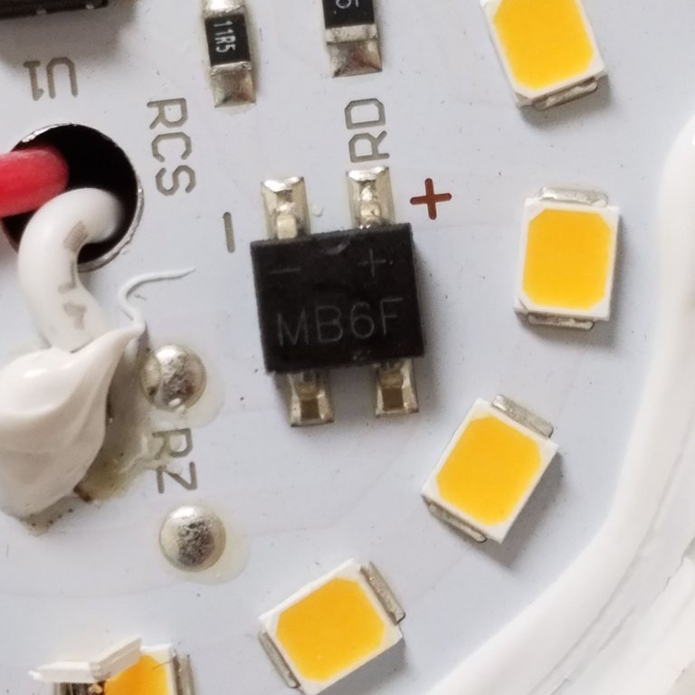
This device is called the MB6F (as you can clearly see), and is actually a full-wave rectifier. The device is essentially a neatly packaged bundle of four semiconductor diodes. Diodes only pass electrical current in one direction (and block it in the other). By using four diodes, you can construct a device that will convert an AC input wave (which oscillates between negative and positive voltages) into an all-positive (DC) waveform that contains all of the original wave. It's kind of like taking the absolute value of the input AC voltage: Once passed through the MB6F, all of the wave will be positive and it can be used like a battery being turned on and off. If you're interested, the datasheet for a similar device can be found here.
LEDs, being diodes, only work in one direction, so the MB6F rectifier turns the input AC into DC for the LEDs. Surprisingly, it seems like it is taking the full force of the 120 volts RMS current from the wall, which is kind of surprising given how tiny this device is.
The other IC is a kind of LED controller chip. It is shown below:
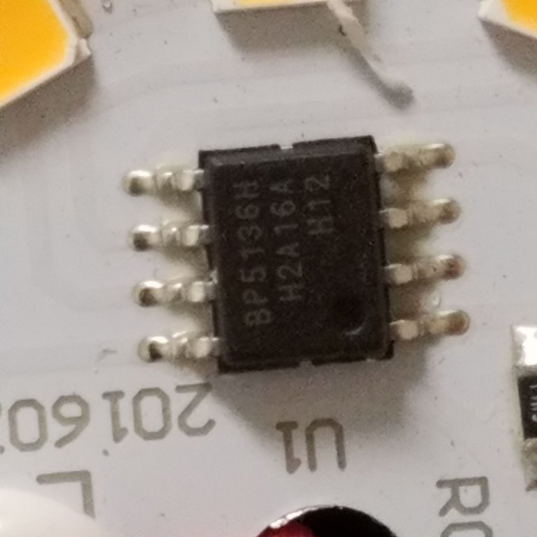
After digging up a datasheet, I found that this is a high-voltage LED controller. That is, it can take in a pretty high voltage (up to several hundred volts) and output semi-constant current for the LEDs to run. Here is the relevant datasheet. Funnily enough, there's a reference circuit on the very first page of this datasheet that looks almost exactly like this LED's circuit. I don't want to include it here since it's marked proprietary, but if you click on the above link you can see a circuit containing ... one full-wave rectifier, the controller chip, two resistors, and a bunch of LEDs ... exactly like the LED I'm currently taking apart. Seems that our friends the manufacturers may have been just a bit lazy - but really, there's nothing wrong with using reference designs.
The short of it is that this larger chip serves to convert input high voltage (~120V DC) into constant, low current for the LEDs.
And with that, we essentially have the entire circuit. The traces are too hidden for me to easily draw a schematic, but the circuit itself is extremely similar if not totally identical to the reference circuit in the LED controller datasheet. It's kind of cool that they were able to power all of these low-voltage LEDs off of the wall using only four components, two of which are resistors (well, plus a fuse). If the controller datasheet is to be believed, the surface mount resistors shown in the original picture of the device are there to regulate the current output from the IC.
And that's how a $1 LED bulb works. This post was a bit more brief than I originally expected, notably because I didn't expect to find just four components inside. Unfortunately I can't explain all of the inner workings of the second IC as they don't provide equivalent schematics. More expensive LED bulbs are likely going to be much more complicated. I hope you've learned something new!
If you have any questions, or comments, or corrections, please let me know below.
Thanks for reading!
All images used in this post are my own. You are welcome to use them with credit.
Cool, do you know what the voltage drop current rating is for those LED's? I can see them handy for "repurposement".
If I'm interpreting the datasheet correctly, they may not actually be stepping down the voltage at all after its rectified, in which case each LED will have a drop of 120/14 = 8.5 volts. The current looks to be 80 mA through the LED string off of 120VAC. I'm unfortunately unable to directly measure it without taking off one of the LEDs, which would be quite difficult and I would have to use soldering equipment in one the labs.
Thats another interesting posts shared by you @ proteus-h thanks for sharing ..keep posting the same.
Very interesting indeed. Although this setup has the drawback, that, when the fuse fails for some reason, the entire bulb becomes useless. Even if nothing is wrong with any of the LEDs or the circuitry.
I guess that this problem could be better in a more expensive bulb, but I wouldn't count on it.
Being A SteemStem Member
The reason for an LED light to be cheaper is its easy availability and low circuit consumption for making. In my lab I use integrating sphere to study the nature and effects of the lights. I have seen that led light gives a less light impression on surroundings, unlike the tube lights. So, it is a more reliable source of light to know the nature of the light through such a lab instrument.