ESPAÑOL
Hola , un saludo para todas esas personas creativas y dinámicas de esta comunidad, deseo que todos esten bien. Hoy quiero compartir con ustedes la forma y los pasos que utilicé para construir un gadget para mi teléfono celular, convirtiéndolo en un control remoto universal con el que puedo gobernar casi la totalidad de los aparatos electrónicos que tengo en casa, siempre y cuando contengan un receptor infrarrojo (IR).
Esta idea no es totalmente de mi autoría, pues en internet ya existen algunos proyectos DIY similares, sin embargo el control remoto de mi TV se averió y en estos momentos no tengo la pieza de repuesto para repararlo y me entusiasmó la idea de construir con materiales reciclados un plug IR para el teléfono celular, similar a los que se muestran en muchos videos de internet, pero dándole mi toque personal.
De esta forma puedo gobernar todos los aparatos electrónicos de mi casa desde el celular, utilizando el plug IR y una aplicación móvil.
A continuación te diré los materiales necesarios para materializar está idea y el paso a paso de como hacerlo.
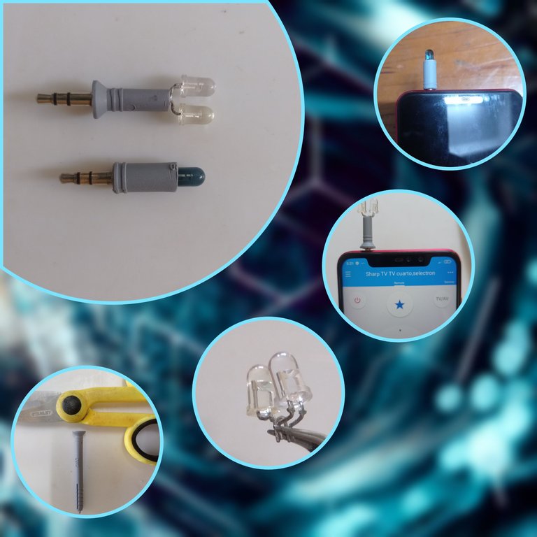
Materiales reciclados que utilicé.
1-Tacos de golpe de 6x60mm y 8x100mm.
2- Conector de audio analógico de 3.5mm reciclado de un par de audífonos en desuso.
3-Diodos LED IR reciclados de algunos controles remotos en desuso.
4- Alambres finos con revestimiento.
A continuación describiré los pasos para hacer este conector IR de 3.5mm para control remoto universal empleando nuestro celular.
PASO A PASO
1-Extraer los diodos IR de las placas electrónicas del los controles remotos en desuso.
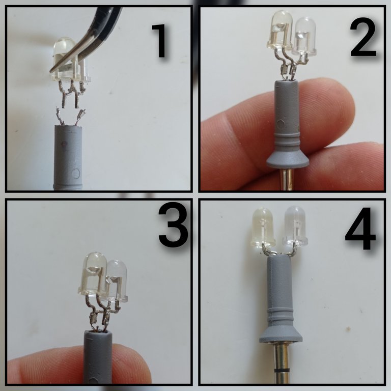
2- Una vez que se extraen los diodos IR se deben soldar las patas de un diodo con las patas del otro diodo de forma antiparalela. Para una mayor comprensión de mi explicación numerare los diodos, por lo que los llamaré diodo 1 ( D1) y diodo 2 (D2). Cada diodo tiene dos patas, una es el ánodo y la otra es el cátodo, para unir los dos diodos LED IR se debe soldar el ánodo en D1 con el cátodo en D2 y el cátodo en D1 con el ánodo en D2. En las próximas imágenes se muestran los pasos descritos anteriormente y se describe como identificar el ánodo y el cátodo del LED IR.
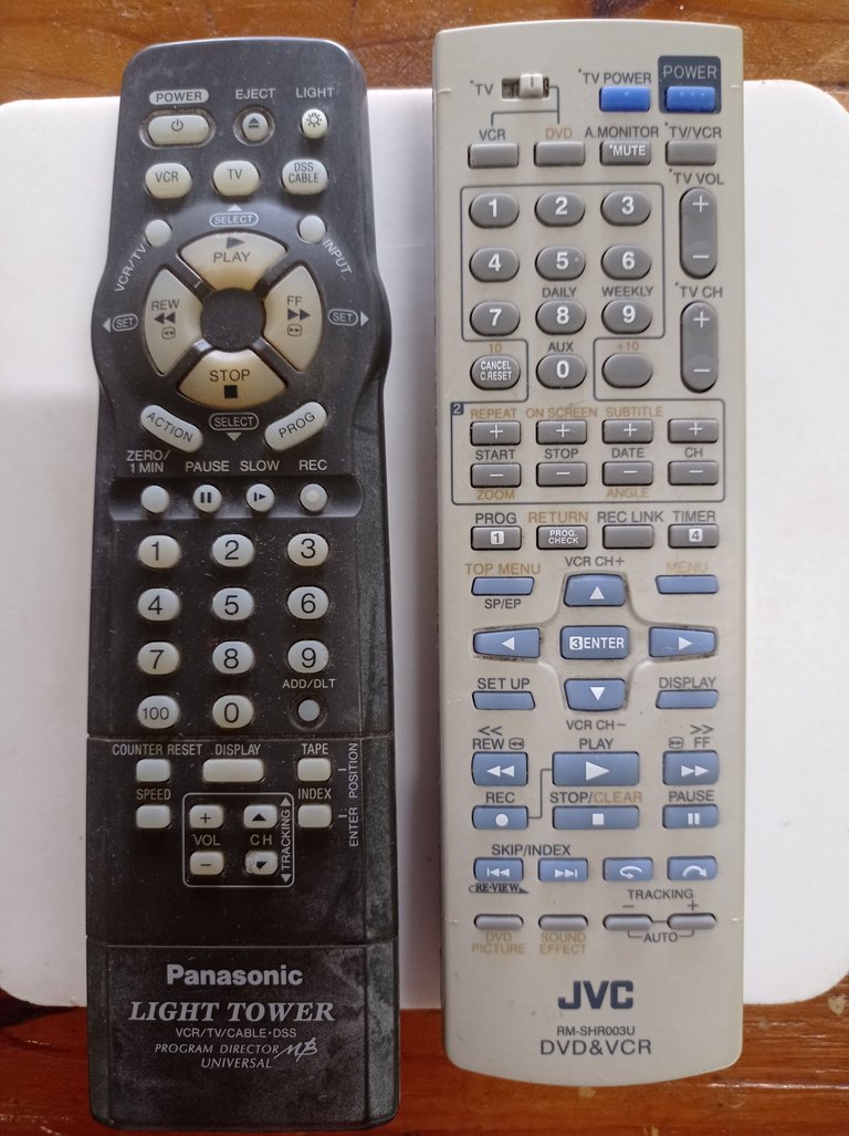
Controles remotos en desuso
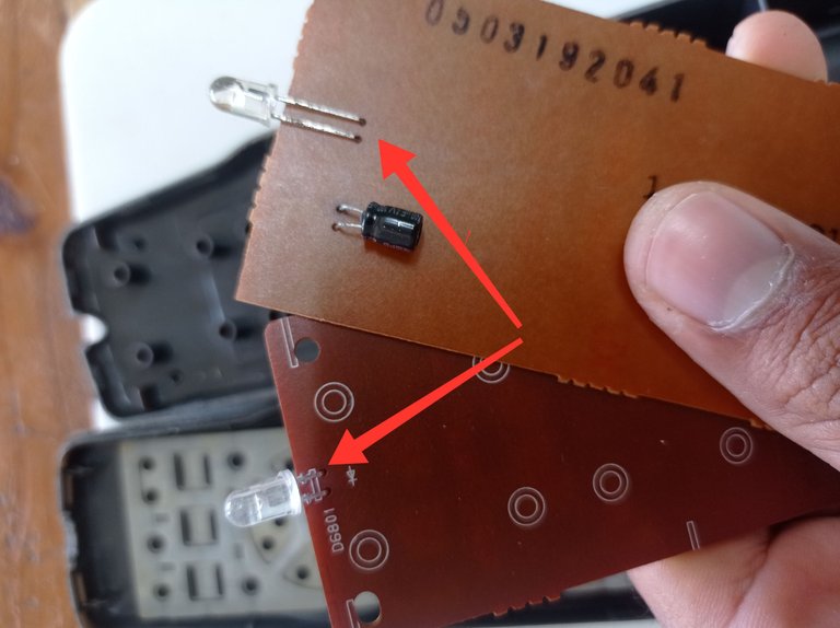
Placas electrónicas de los controles remotos, con los diodos LED IR señalados, se extraen con ayuda de un cautín, o picar las patas con una pinza de corte
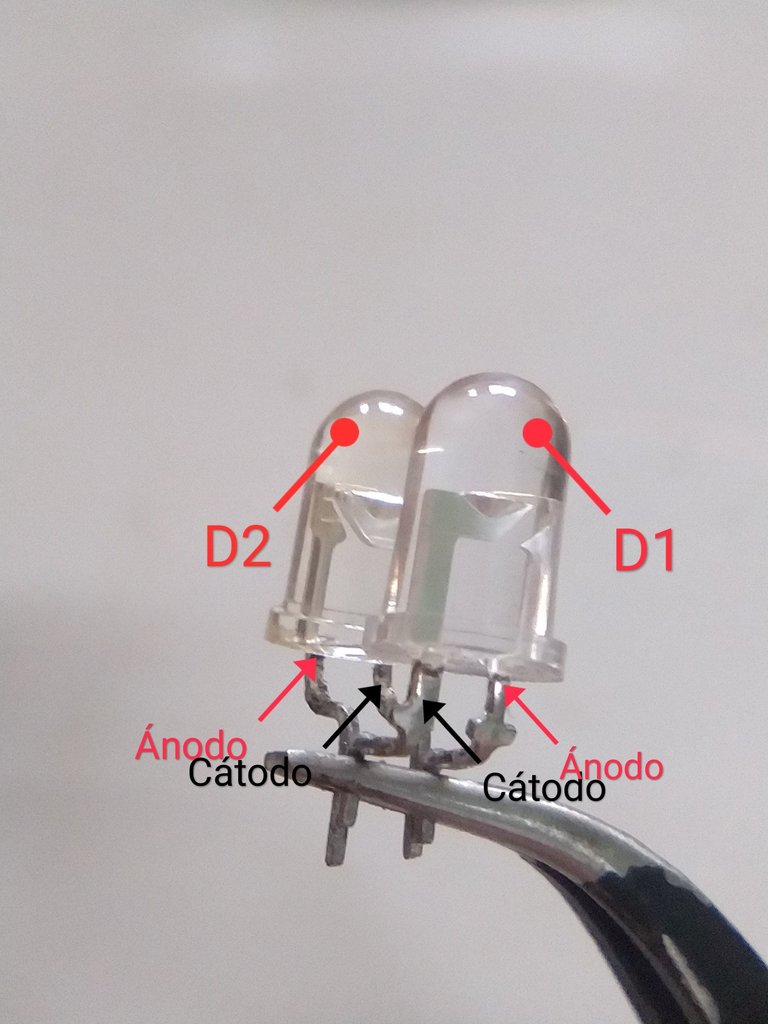
Unión de los diodos D1 y D2, se observa como el ánodo en D1 se une al cátodo en D2 y el cátodo en D1 con el ánodo en D2.
En el interior del diodo se observa una pata con mayor superficie que la otra, esta corresponde al cátodo y la de menor superficie corresponde al ánodo, también se pude identificar el catálogo mirando el cuerpo del diodo, el cual posee un corte plano por la superficie exterior del mismo, este corte coincide con el cátodo
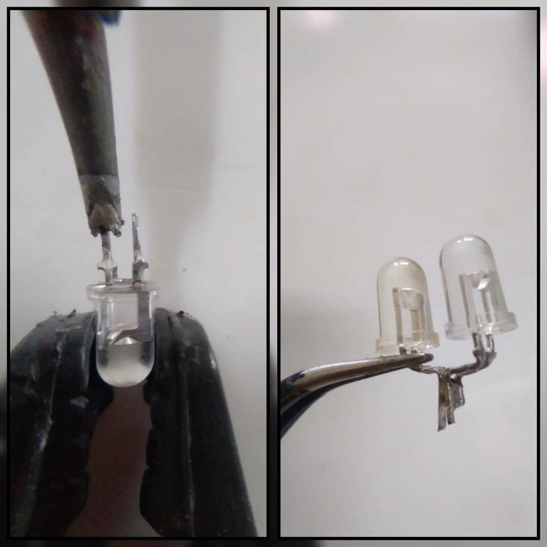
Con ayuda de una presilla de tender ropa sujeté los LEDs para soldarlos con el cautín, quedando como se muestra en la segunda imagen del collage
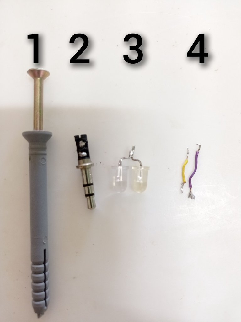
3- Cómo tercer paso, preparé el conector de audio analógico de 3.5mm, cómo se describe en las siguientes imagenes.
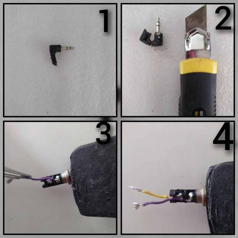
1-Conector de audio analógico de 3.5mm con tres polos( canal izquierdo, canal derecho y tierra)
2- Con ayuda de un cúter se abre el recubrimiento de goma que protege al conector y se extrae el mismo.
3- Alambre violeta soldado al canal derecho del conector.
4 - Alambre amarillo conectado al canal izquierdo y violeta al canal derecho (La tierra no es necesario usarla).
4- El cuarto paso consiste en preparar el taco de golpe de 6x60 mm, para ello se debe cortar un trozo de la cabeza del taco de aproximadamente 2cm, este servirá para alojar el conector y los cables en su interior.
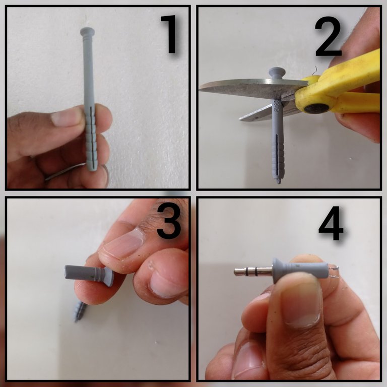
1-Taco de golpe de 6x60mm.
2- Con ayuda de una tijera cortar 2cm del taco medidos desde la cabeza.
3- Taco de 2cm de largo.
4- Introducir por la cabeza del taco el conector y los cables.
5- El quinto paso sería unir con soldadura de estaño los cables que sobresalen por el extremo opuesto a la cabeza del taco con las uniones de las patas de los diodos LED IR, (D1yD2).
1-Acercar los diodos a los cables que sobresalen del taco para su posterior soldadura.
2-Soldar en las uniones de las patas de los LED, los cables que sobresalen del taco.
3-LEDs soldados a los cables
4- Acomodar los cables y los LED dentro del taco, se pude poner pegamento si fuera necesario para garantizar una unión más sólida.
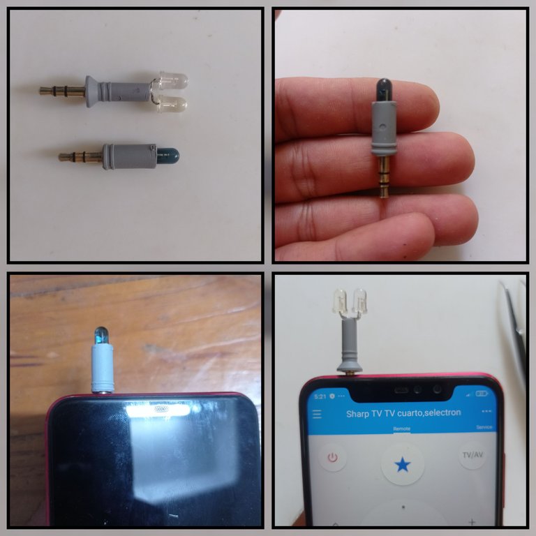
Aquí se muestra el conector que describí anteriormente y junto a él otro conector que preparé utilizando los mismos pasos pero usando un solo LED IR y un taco de golpe de 8 x 100 mm
Ya está listo el conector, lo siguiente es configurar la aplicación móvil.
La aplicación que utilicé es una llamada Control Remoto: Zaza Remote y les dejaré la dirección de descarga desde la play store en el siguiente link. Una vez descargada es necesario configurarla.
Configurando la app:
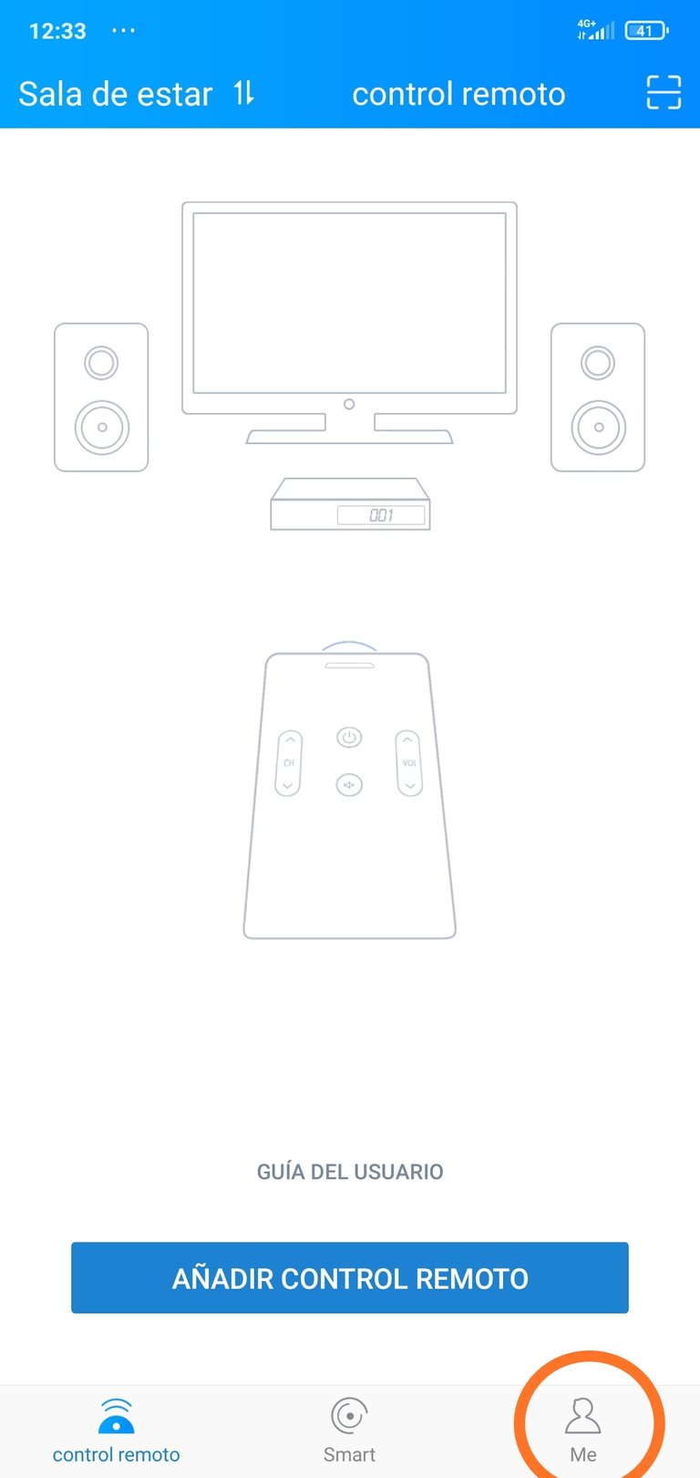
*Colocamos el conector IR en el teléfono y abrimos la aplicación móvil.
Pinchamos en la opción Me *
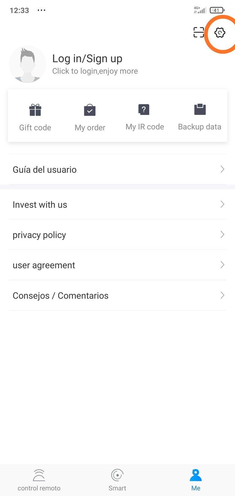
Pinchar en la opción de configuración(Rueda dentada)
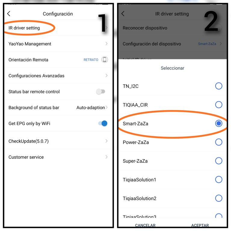
1-Pinchar en la opción IR driver setting
2- Seleccionar la opción Smart-Zaza y le damos aceptar
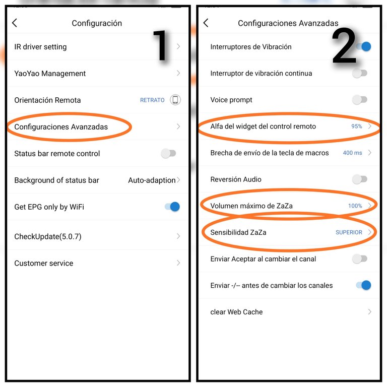
1- Seleccionar Configuración Avanzada.
2- Establecer los parámetros como se muestran en las opciones señaladas.
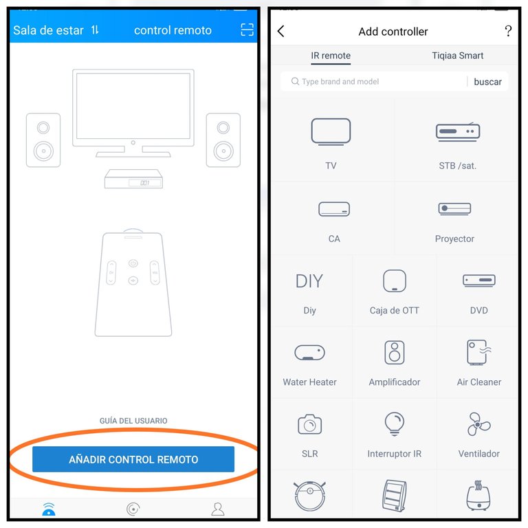
Luego se pincha en Añadir control remoto se selecciona el tipo de electrodoméstico que se desea gobernar, así como la marca correspondiente y se configura siguiendo los pasos que se van mostrando en la aplicación
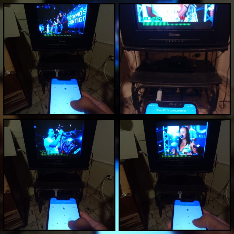
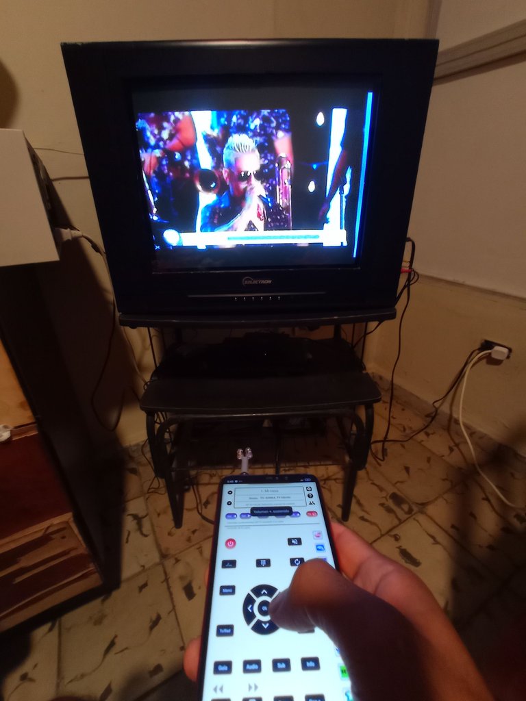
En las siguientes imágenes les muestro las pruebas que hice con mi TV y mi caja decodificadora de Televisión Digital Terrestre.(TDT)
Pueden ver qué pruebo los dos conectores que construí y empleo una aplicación adicional que fue desarrollada acá en Cuba específicamente para los TV y decodificadores TDT comercializados aquí.
Probando los conectores IR
Bueno amigos de esta forma se puede resolver cuando no se tenga el control remoto de algún electrodoméstico que necesitemos gobernar. Es cierto que la mayoría de los teléfonos de gama alta y algunos de la gama media traen incorporado un LED IR en su placa por lo que no necesitan de un conector como el que les muestro, pero hay bastantes teléfonos celulares que no traen incorporado este aditamento para gobernar los aparatos que tienen receptores IR, por eso les muestro esta forma en la que solucioné mi problema y les doy a ustedes una sugerencia de como pudieran darle un uso adicional a su celular.
Un saludo para ti que me lees, y hasta el próximo post 😉.
Las imágenes son de mi autoría y fueron tomadas con un celular Xiaomi Redmi Note 6 Pro.
Imágenes editadas en la aplicación "Galería" del teléfono,aplicación Foto Collage-GridArt y "GIF Maker"
Texto traducido al inglés en el traductor Deepl
Puedes verme en Facebook
ENGLISH
Hello, greetings to all those creative and dynamic people in this community, I wish you all well. Today I want to share with you the way and the steps I used to build a gadget for my cell phone, turning it into a universal remote control with which I can control almost all the electronic devices I have at home, as long as they contain an infrared receiver (IR).
This idea is not entirely my own, as there are already some similar DIY projects on the internet, however the remote control of my TV broke down and at the moment I do not have the spare part to repair it and I was excited about the idea of building with recycled materials an IR plug for the cell phone, similar to those shown in many videos on the internet, but giving it my personal touch.
This way I can control all the electronic devices in my house from my cell phone, using the IR plug and a mobile application.
Next I will tell you the materials needed to materialize this idea and the step by step of how to do it.
Recycled materials I used.
1- 6x60mm and 8x100mm punching blocks.
2- 3.5mm analog audio connector recycled from a pair of disused headphones.
3-Recycled IR LEDs from some disused remote controls.
4- Thin coated wires.
()
Below I will describe the steps to make this 3.5mm IR connector for universal remote control using our cell phone.
STEP BY STEP
1-Remove the IR diodes from the electronic boards of the disused remote controls.
2- Once the IR diodes are removed, solder the legs of one diode with the legs of the other diode in an antiparallel way. For a better understanding of my explanation I will number the diodes, so I will call them diode 1 (D1) and diode 2 (D2). Each diode has two legs, one is the anode and the other is the cathode, to join the two IR LED diodes you must solder the anode at D1 with the cathode at D2 and the cathode at D1 with the anode at D2. The following pictures show the steps described above and describe how to identify the anode and cathode of the IR LED.
Remote controls in disuse
Electronic boards of the remote controls, with the IR LEDs marked, are removed with a soldering iron, or the legs can be cut off with cutting pliers.
Union of the diodes D1 and D2, it can be seen how the anode in D1 joins the cathode in D2 and the cathode in D1 with the anode in D2.
Inside the diode there is a leg with a larger surface than the other, this corresponds to the cathode and the smaller surface corresponds to the anode, you can also identify the catalog looking at the diode body, which has a flat cut on the outer surface of it, this cut coincides with the cathode.
With the help of a clothespin I held the LEDs to solder them with the soldering iron, as shown in the second image of the collage.
3- As a third step, I prepared the 3.5mm analog audio connector, as described in the following pictures.
1- 3.5mm analog audio connector with three poles (left channel, right channel and ground).
2- With the help of a cutter the rubber cover that protects the connector is opened and the same one is extracted.
3- Violet wire soldered to the right channel of the connector.
4 - Yellow wire connected to the left channel and violet to the right channel (The ground is not necessary to use it).
4- The fourth step is to prepare the 6x60 mm punching block, to do this, cut a piece of the head of the block of approximately 2cm, this will serve to house the connector and cables inside it.
1- 6x60mm punching block.
2- With the help of a scissors cut 2cm of the block measured from the head.
3- Plug 2cm long.
4- Insert the connector and the cables through the head of the plug.
5- The fifth step would be to solder the wires that protrude from the opposite end of the plug head to the junctions of the legs of the IR LEDs (D1and D2).
1-Anchor the diodes to the wires that protrude from the block for later soldering.
2-Solder the wires that protrude from the plug to the joints of the legs of the LEDs.
3-LEDs soldered to the wires
4-Accommodate the wires and LEDs inside the block, you can put glue if necessary to ensure a more solid union.
Shown here is the connector I described above and next to it another connector that I prepared using the same steps but using a single IR LED and an 8 x 100 mm tapped socket
The connector is ready, the next step is to configure the mobile application.
The application I used is an application called Remote Control: Zaza Remote and I will leave you the download address from the play store in the following link. Once downloaded it needs to be configured.
Configuring the app:
Place the IR connector on the phone and open the mobile application.
Click on the Me option
Click on the configuration option (cogwheel).
1-Click on the option IR driver setting.
2-Select the Smart-Zaza option and click on accept.
1- Select Advanced Configuration.
2- Set the parameters as shown in the indicated options.
Then click on Add remote control, select the type of appliance you wish to control, as well as the corresponding brand and configure it following the steps shown in the application.
In the following images I show you the tests I did with my TV and my Digital Terrestrial Television (DTT) decoder box.
You can see that I test the two connectors that I built and I use an additional application that was developed here in Cuba specifically for the TV and DTT decoders marketed here.
Testing the IR connectors
Well friends this way you can solve when you do not have the remote control of any appliance that we need to govern. It is true that most high-end phones and some of the mid-range have a built-in IR LED on their board so they do not need a connector like the one I show you, but there are quite a few cell phones that do not bring built-in this attachment to govern the devices that have IR receivers, so I show you this way in which I solved my problem and I give you a suggestion of how you could give an additional use to your cell phone.
Greetings to you who read me, and until the next post 😉.
The images are of my authorship and were taken with a Xiaomi Redmi Note 6 Pro cell phone.
Images edited in the "Gallery" application of the phone,Photo Collage-GridArt application and "GIF Maker ".
Text translated to English in Deepl translator.
You can see me on Facebook
Congratulations @darknapol! You have completed the following achievement on the Hive blockchain And have been rewarded with New badge(s)
Your next target is to reach 20 posts.
You can view your badges on your board and compare yourself to others in the Ranking
If you no longer want to receive notifications, reply to this comment with the word
STOPTo support your work, I also upvoted your post!
Check out our last posts:
Yay! 🤗
Your content has been boosted with Ecency Points, by @hive-130560.
Use Ecency daily to boost your growth on platform!
Support Ecency
Vote for new Proposal
Delegate HP and earn more
Thanks for the support, greetings to the team
Reviewed and Approved for an Ecency boost. Keep up the good work.
Hello, thanks for the support, greetings to the team.
You're welcome
Wow, jamás me hubiese pasado por la cabeza! 🤯
Hola @danigada saludos, gracias por comentar, este proyecto me resolvió mi problema que no tenía control remoto, ahora pudo gobernar todo desde la comodidad del celular. Saludos