Hi Hivers! How is everything? On this occasion I will let you know part of the project which I am carrying out. It's an idea that came to my mind about a year ago, and to be honest I've spent a little bit of my time developing it since then. I intend to commercialize this project, but before that, I must follow a series of steps and procedures that guarantee its quality and, in turn, that it is attached to international standards.
Se trata del diseño de un tomacorriente tipo NEMA 5-15R, el cual internamente se encuentra protegido contra las fluctuaciones en la red eléctrica, evitando así posibles daños a los aparatos eléctricos conectado a dicho receptáculo. En pocas palabras, es un regulador de tensión integrado a un tomacorriente. Esta idea vino a mi cabeza luego se sufrir varias molestias por las fallas en la red del sistema eléctrico nacional venezolano, las cuales constantemente afectan los dispositivos que dependen de dicha red.
It is the design of a NEMA 5-15R type outlet, which is internally protected against fluctuations in the electrical network, thus avoiding possible damage to electrical devices connected to said receptacle. Simply put, it is a voltage regulator built into an outlet. This idea came to my head after suffering various annoyances due to failures in the Venezuelan national electrical system network, which constantly affect the devices that depend on said network.
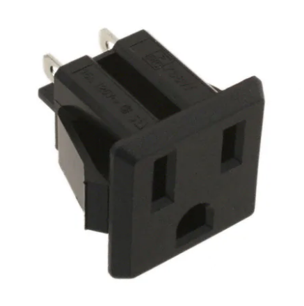
NEMA 5-15R Receptacle
This image was taken from Digikey.com, electronic components distributor page
Debido a eso, decidí que era hora de sacarle provecho mi ingeniería y poner manos a la obra para empezar a desarrollar un aparato que ayude a evitar daños a los equipos del hogar. Primero empecé determinando las características con las cuales iba a contar el tomacorrientes, posteriormente realicé el diseño del diagrama esquemático, los cálculos correspondientes, etc. Seguido a ello, comencé el diseño del circuito impreso y ahora que ya está prácticamente terminado se los quiero enseñar, ya que me siento bastante bien con los resultados obtenidos hasta ahora.
Because of that, I decided it was time to take advantage of my engineering and get down to work to start developing a device that helps prevent damage to household equipment. First, I started by determining the characteristics that the outlet would have, then I made the design of the schematic diagram, the corresponding calculations, etc. Following this, I started the design of the printed circuit and now that it is practically finished I want to show it to you, since I feel pretty good with the results obtained so far.
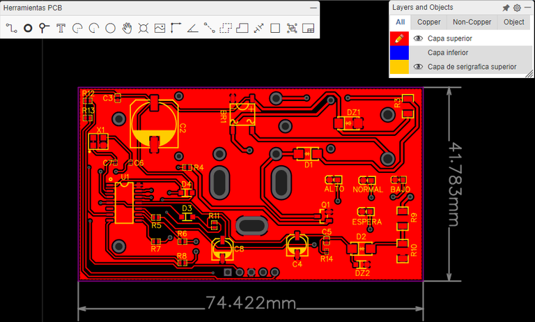
La imagen previa representa la capa superior del PCB.
The preview image represents the top layer of the PCB.
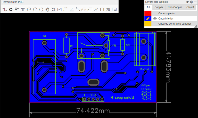
Y ésta representa la cara inferior de la misma, es decir, posee circuitería por ambas caras, ayuda a reducir el tamaño de cierta forma. Esto es apenas una parte del proyecto, me encuentro en las primeras fases, y aún no he llegado a las fase de prueba para determinar posibles errores de diseño.
And this represents the lower face of it, that is, it has circuitry on both sides, it helps to reduce the size in a certain way. This is just a part of the project, I am in the early stages, and I have not yet reached the testing phase to determine possible design errors.
Para concluir, doy las gracias por el tiempo que se tomanlo miembros en leer dicha publicación y en las posteriores iré detallando los adelantos del tomacorrientes protegido. El programa usado para el diseño del diagrama esquemático y la PCB se llama EasyEDA
To conclude, I thank each member for the time that each member takes to read this publication and in the subsequent ones I will detail the advances of the protected electrical outlet. The program used for the design of the schematic diagram and the PCB is called EasyEDA
Congratulations @bohorquez19! You have completed the following achievement on the Hive blockchain and have been rewarded with new badge(s) :
Your next target is to reach 100 upvotes.
You can view your badges on your board and compare yourself to others in the Ranking
If you no longer want to receive notifications, reply to this comment with the word
STOPCheck out the last post from @hivebuzz: