Hello, friends of this wonderful community. It's Tuesday, hooray!! And it feels good to be back after a series of lectures and the stress of having to queue for a long period of time to get a cab after class to get home.
I will be discussing a project that my departmental colleague and I worked on, as well as the project's outcome.

AIM
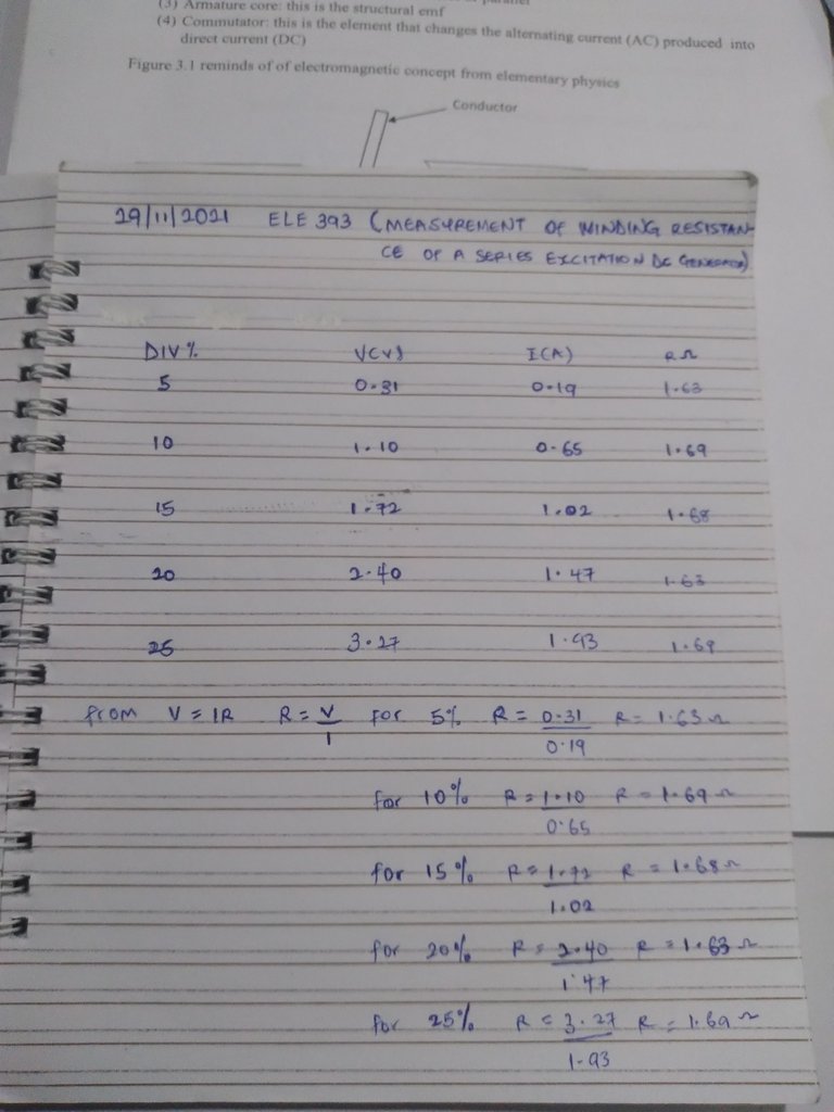
Measurements of winding resistance of a series excitation DC Generator
OBJECTIVES
To calculate the winding resistance of series excitation of DC Generator using Volt-ampere method.
THEORETICAL REVIEW
The field current is connected in series with the armature and is transverse by the total load current. This method, In which the excitation is proportional to the load current, is unsuitable for normal Generators; the internal voltage drop is directly dependent on the load current and until saturation is approached is almost proportional to it.
COMPONENTS USED IN EXECUTION OF THE EXPERIMENTS
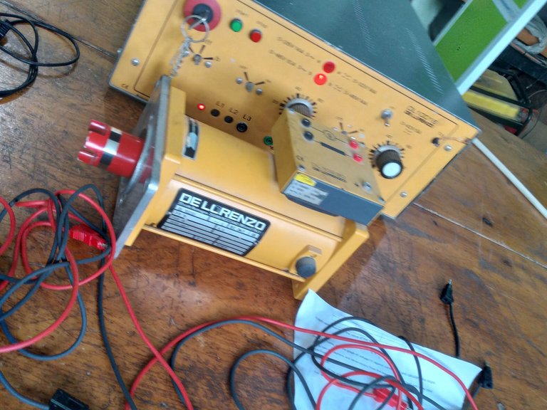
• Variable Dc output source
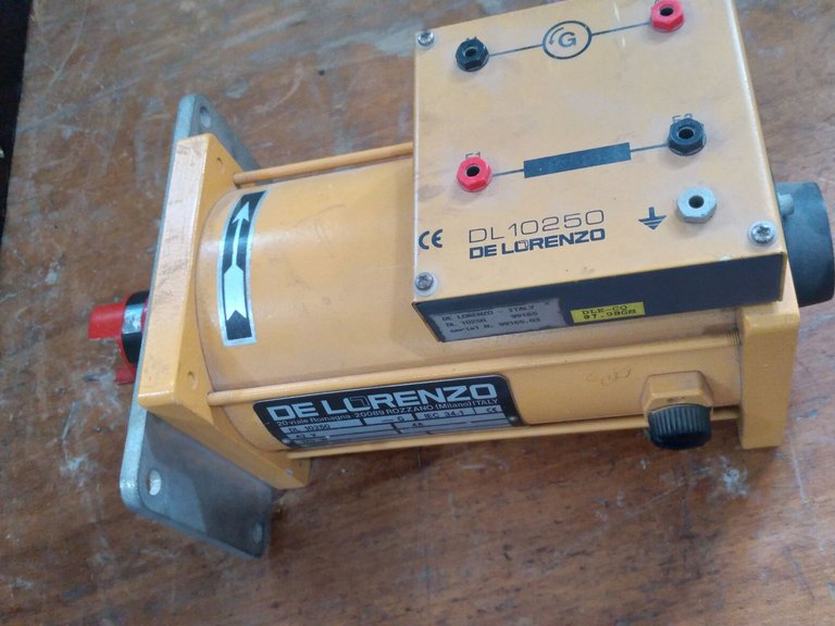
• Series Excitation Dc Generator -DL10230
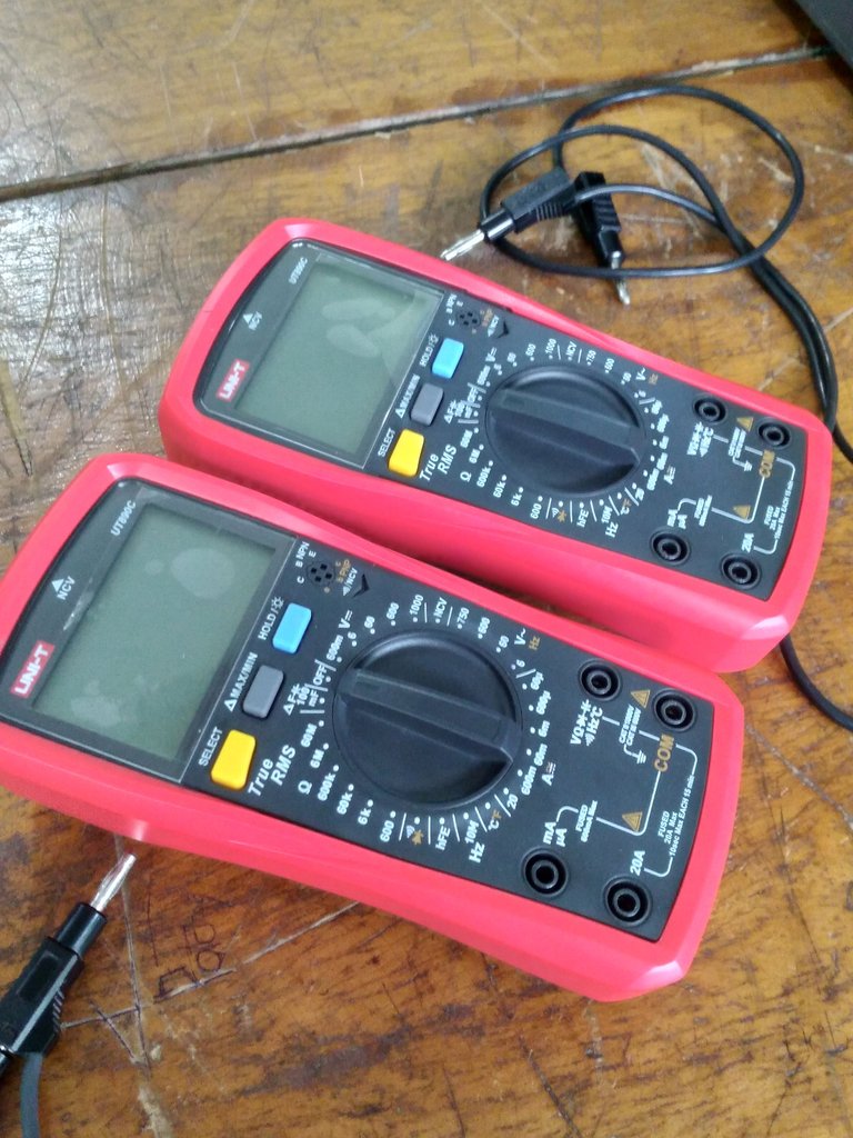
• Voltmeter (0-20v)
• Ammeter (0-10A)
• Tachometer
• connecting leads
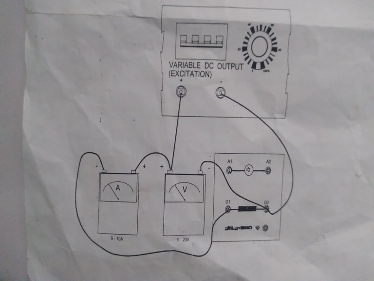
A layout of the connections circuit was Printed for us to Follow and the connections Goes Thus;
The Positive terminal of the Variable Dc output was connected to the positive of the Voltmeter,The positive of the Voltmeter to positive probe of the Ammeter, the negative Terminal of the Ammeter is connected to the D1 terminal of the series excitation DC Generator-DL10230 While the Negative terminal of the Variable Dc output is connected to D2 of the series Excitation Dc Generator and negative Probe of the Voltmeter respectively.
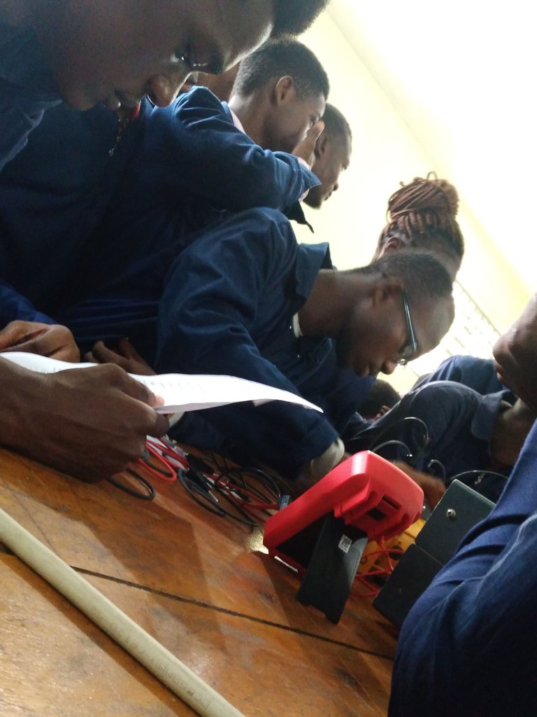
PROCEDURES WE FOLLOWED WHILE EXECUTING THE EXPERIMENTS FOR EACH PERCENTAGE OF THE LOAD
When the circuit shown with heavy lines has been connected with connecting leads, we performed the following operations
STEP 1: I set the controls of the modules to Variable DC output section.
STEP 2: I Opened the circuit breaker and turn the variator knob rotated fully counter clockwise position.
STEP 3: I Connect the Voltmeter, switch on the power supply module by closing the circuit breaker.
STEP 4: I Adjusted the Variable knob in a clockwise direction at a range indicated on the Variable Dc output source and must not exceed 25%, record the values of Voltage (V) and current (I) obtained from the Voltmeter and Ammeter
STEP 5: I recorded the values of current (A) and corresponding values of Voltage (V)
At the end of the Class, I was able to understand the fact that in a Step up Transformers as the number of Turns increases, the voltage increases and current decreases.
Thanks for Reading my Blog.
Engineer in the making 💯💯💯