ENGLISH
Greetings to the community. I will tell you that in the ceiling of the living room of my house I have one of those beautiful crystal lamps that in addition to its lighting function, also adorn the environment, but recently, the last of the three incandescent bulbs with which it works stopped working, so I created a problem because I had no spare parts to replace and leave it functional.
However, I did have an 18 watt LED tube, but I did not want to remove the glass lamp because it would no longer decorate the room, giving me the task of making an adaptation with the materials I have at home, whose process I describe below.
First I will tell you what materials I had at hand, but I could use others, it all depends on what you have at home.
-18 watt LED tube
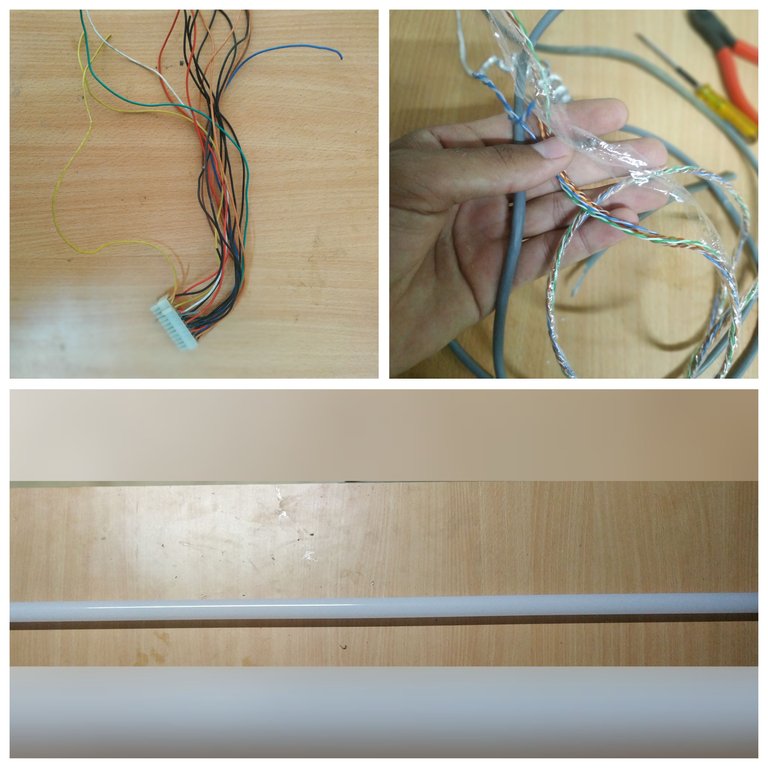
Cables from an old 24-pin ATX socket, from a computer power supply.
-Two meters of Ethernet network cable.
-Silicone tubing.
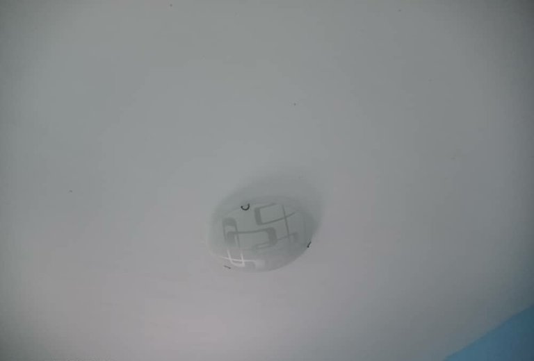
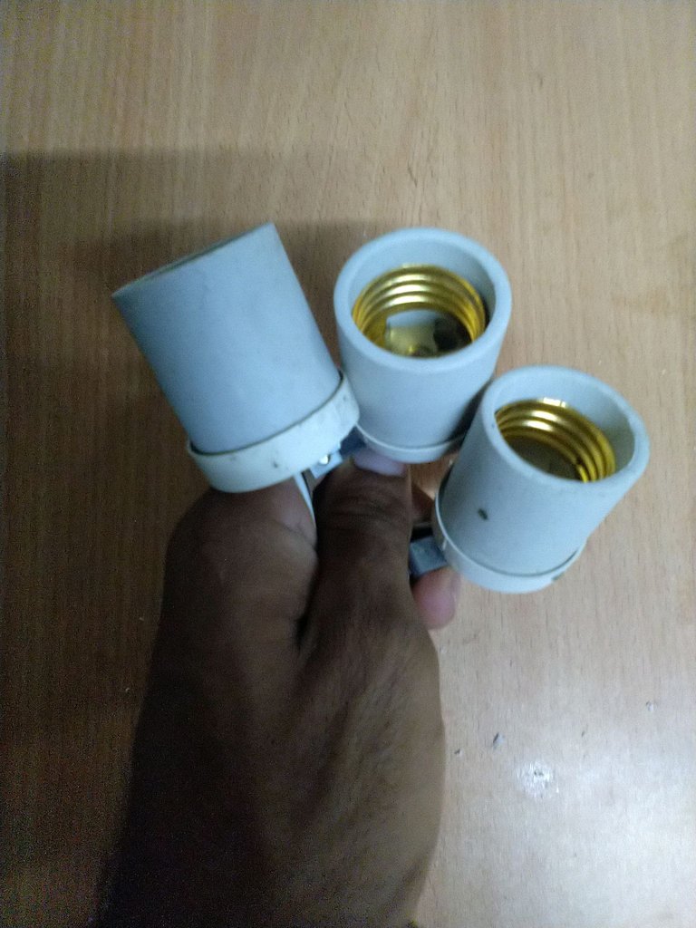
In the following image I show you the base of the glass lamp, on which I will work and add the LED strips as I will describe later.
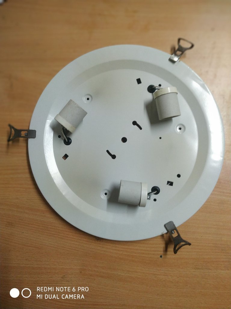
I removed the soquet to recycle them for future use where needed.
Then I disassembled the tube to remove the LED strip inside. In this particular type of tube I needed the use of a hot air gun, but you can use a hair dryer or other tool that allows us to soften the silicone that fixes the end caps of the LED tube. In the following images I show you how to apply heat to the ends I could remove the caps with the help of a screwdriver by prying, you have to do it carefully to avoid damaging the switching power supply that feeds the LED strip.
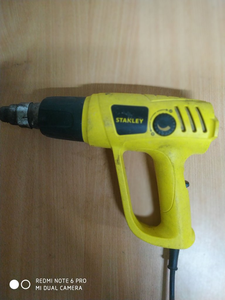
Hot air gun
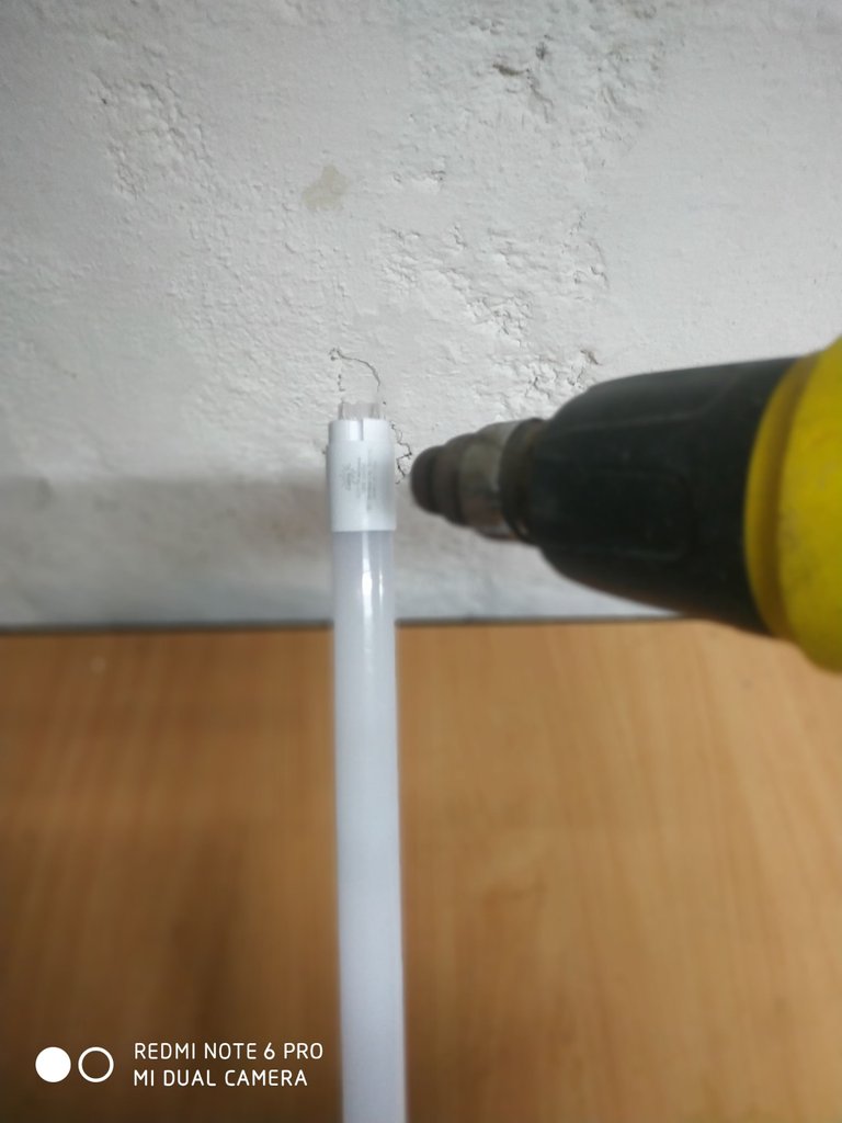
Applying heat to the ends of the tube
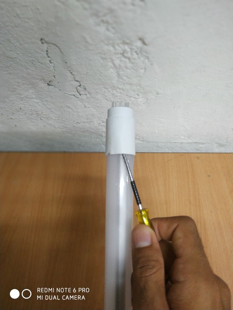
Remove the cover with a screwdriver.
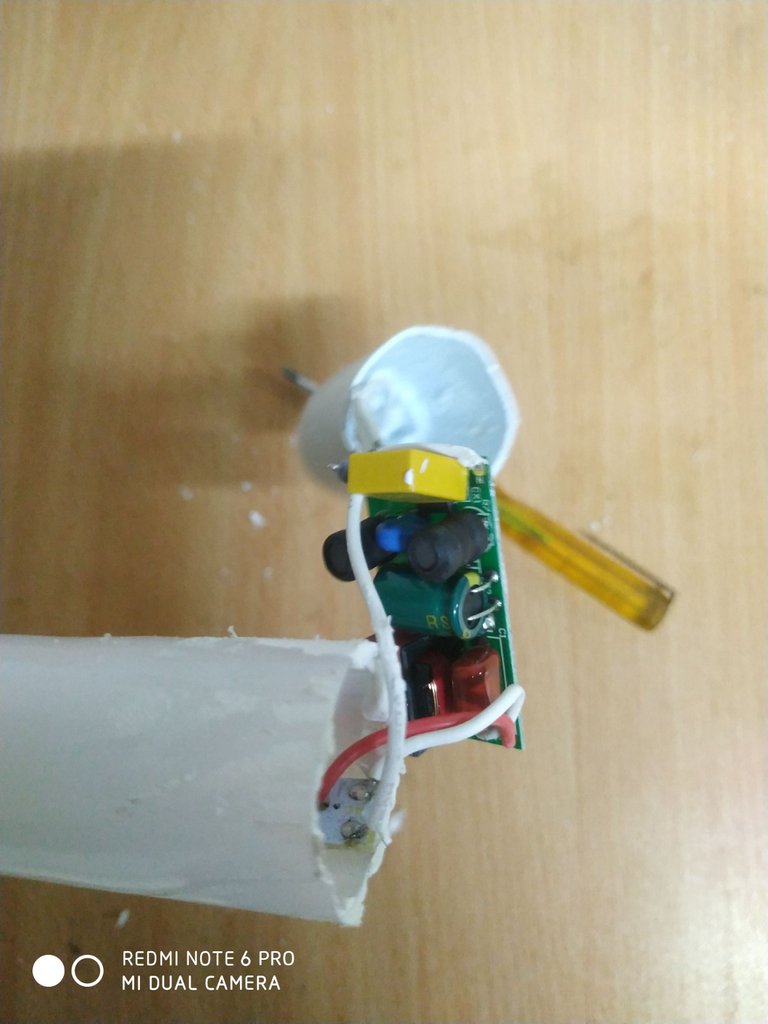
Switch-mode power supply to power the LED strip
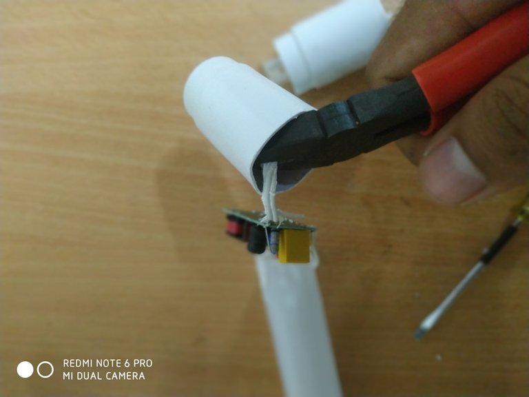
Cut the cable connecting the switch mode power supply to the lid
Cut the cable connecting the switch mode power supply to the lid
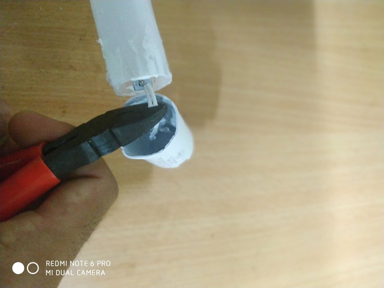
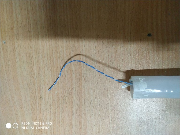
After removing the caps, it was necessary to remove the LED strip which was also attached with silicone to the body of the tube. To remove it without damaging it, I used one of the thin cables containing the Ethernet network cable inside. I made a loop at one end of the cable and inserted the other end through the inside of the tube until it came out at the opposite end. I then wrapped the loop around the end of the LED strip and pulled the opposite end of the cable to separate the LED strip from the body of the tube without damaging it.
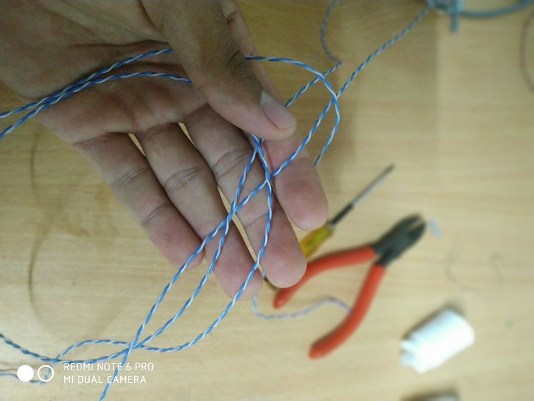
Thin cable to detach the LED strip
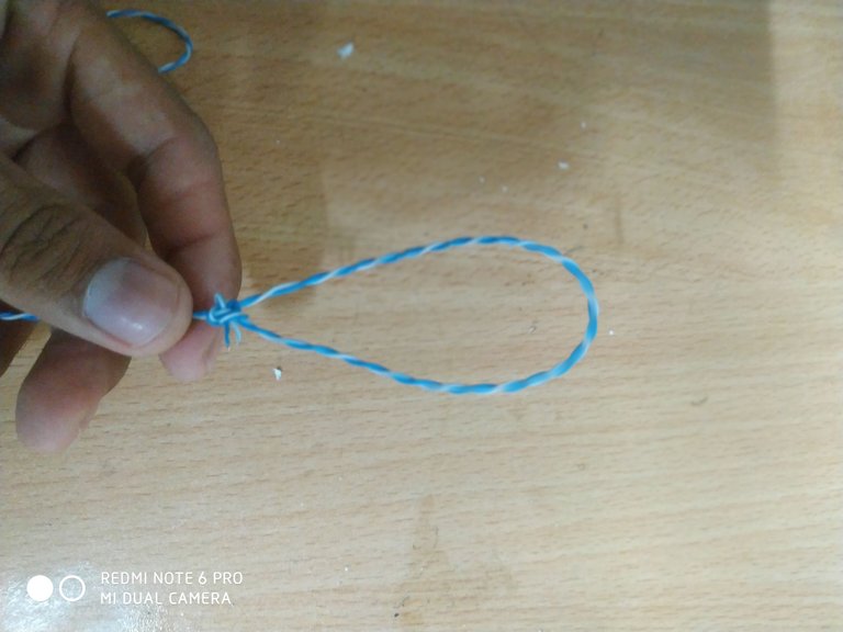
Loop at one end of the cable
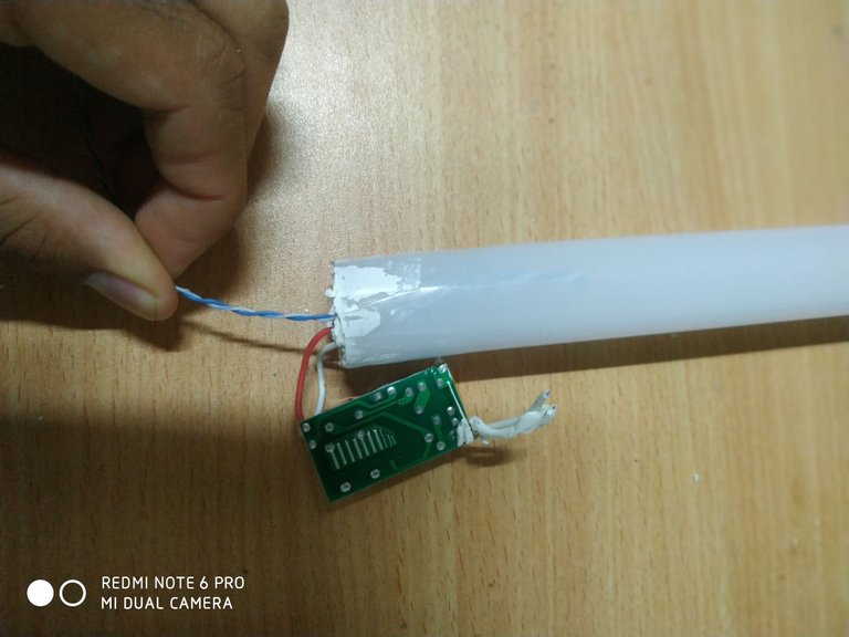
Insert the opposite end of the cable loop through one end of the tube.
Cable end at the opposite end of the tube
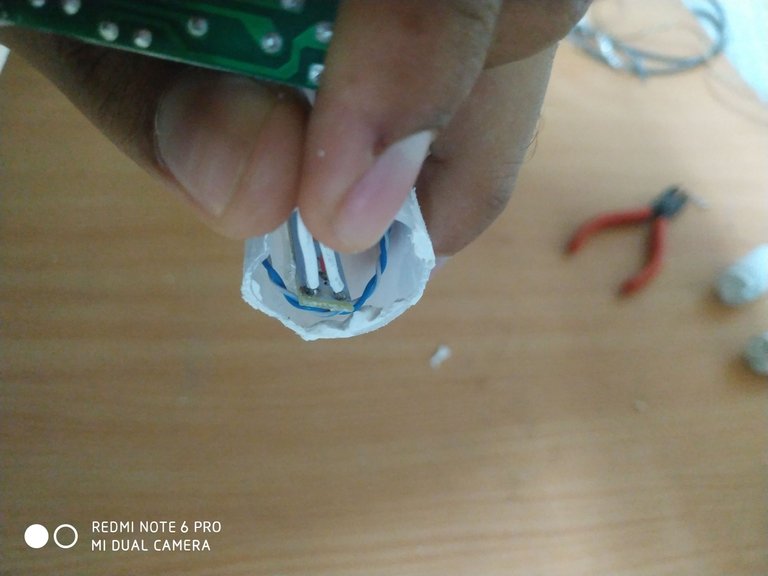
Loop placed at the tip of the LED strip, remaining between it and the body of the tube.
Loop while pulling on the opposite end of the cable
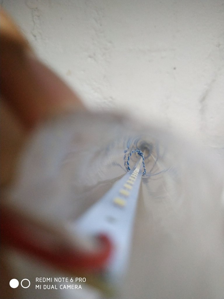
Image during strip removal, from another angle
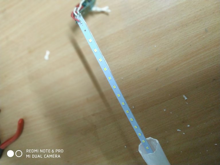
Removal of the strip after complete detachment from the tube body
After extracting the LED strip, I divided it into seven equal parts, with the objective of distributing it in the body of the base of the crystal lamp.
Once the divisions were made in the strip, I identified them in consecutive order and then I joined them again through some jumpers using the wires of the 24-pin ATX socket.
The union was made at each point where I interrupted the copper connection in the strip itself. Then I show it in the following photos for a better understanding.
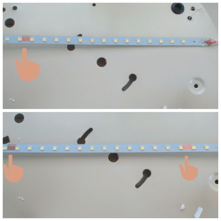
Points on the LED strip where I removed the insulating paint that protects the copper connection, being marked to divide it into seven equal parts.
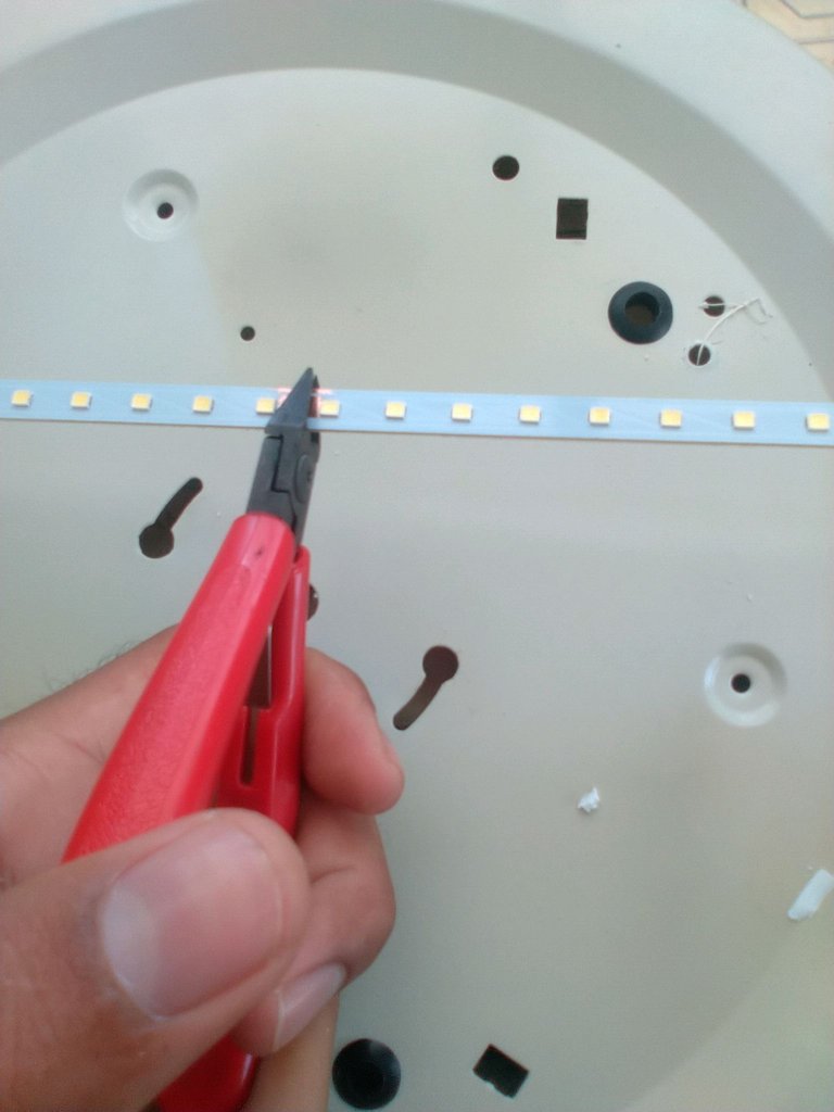
Cutting of the strip at each mark
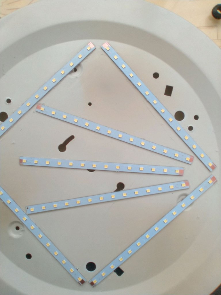
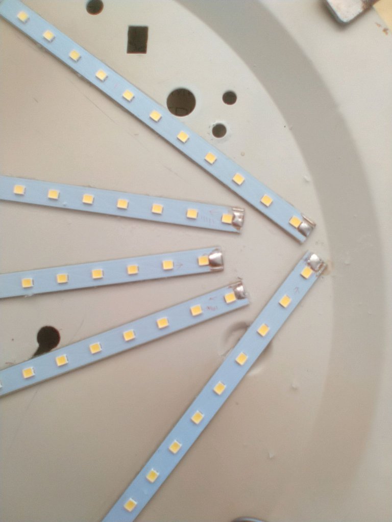
After dividing the strips, I superimposed them on the base of the lamp.
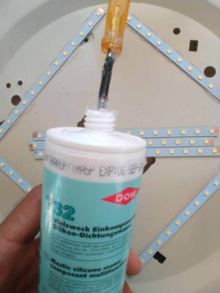
Once each section has been superimposed, silicone is applied to fix them to the base, so that the heat generated by the consumption of the LED diodes is dissipated by the base.
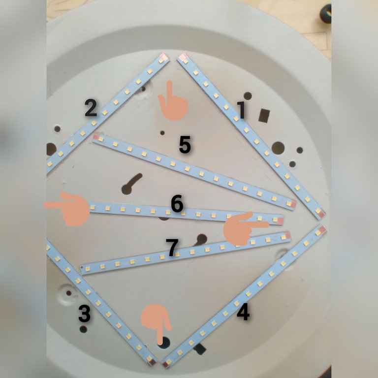
Here the strips are shown in consecutive order, adhered with silicone and the points indicated where the bridges will be made to close the circuit in the same way they were connected before dividing them.
With the aid of a soldering iron, carefully apply solder to the bare copper on the strips, avoiding joining the negative connection with the positive connection.
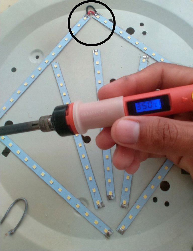
Soldering iron used with temperature at 350 °C and first bridge made, marked in black circle
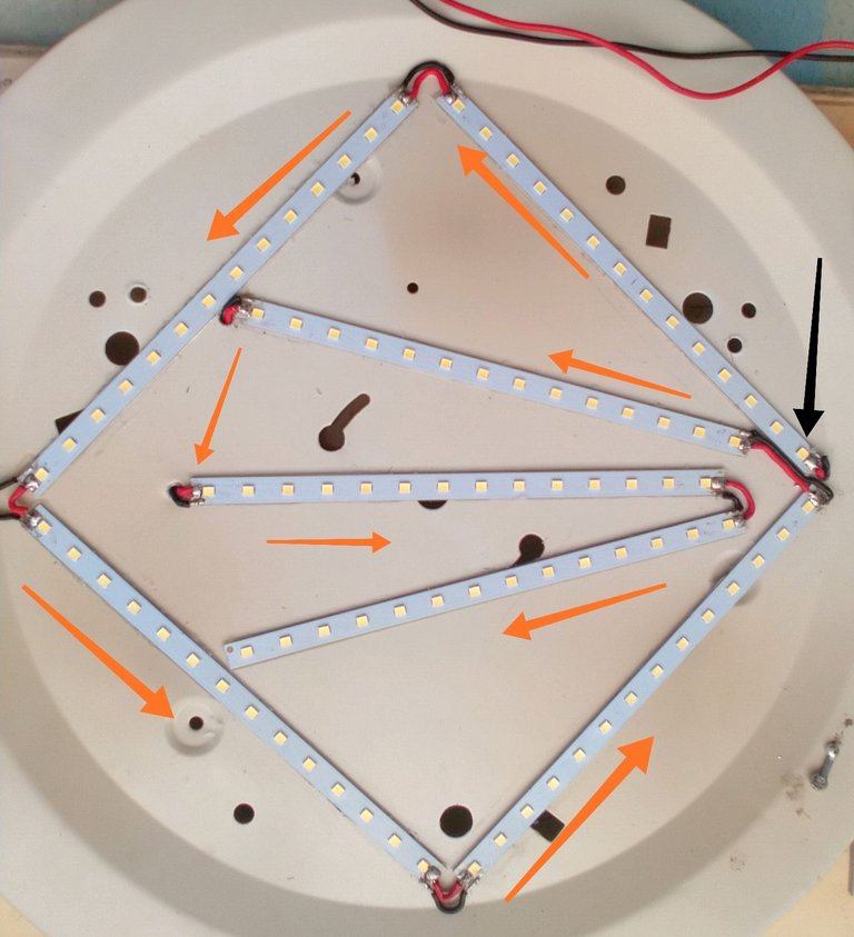
All jumpers completed, the black arrow represents the point where the direct voltage from the switched-mode power supply enters, and the rest of the arrows represent the order in which the strips are joined.
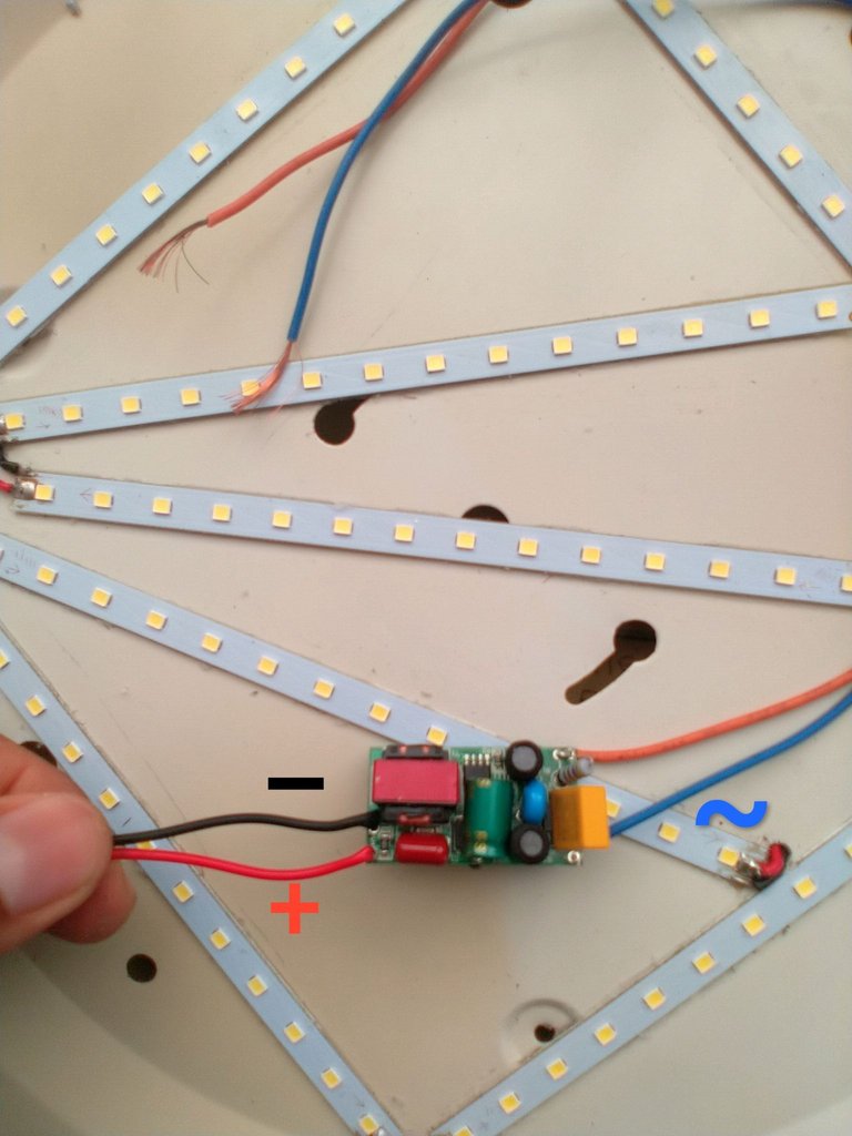
Switching power supply to which the AC input cables (blue and orange) and the DC output cables (red and black) were soldered.
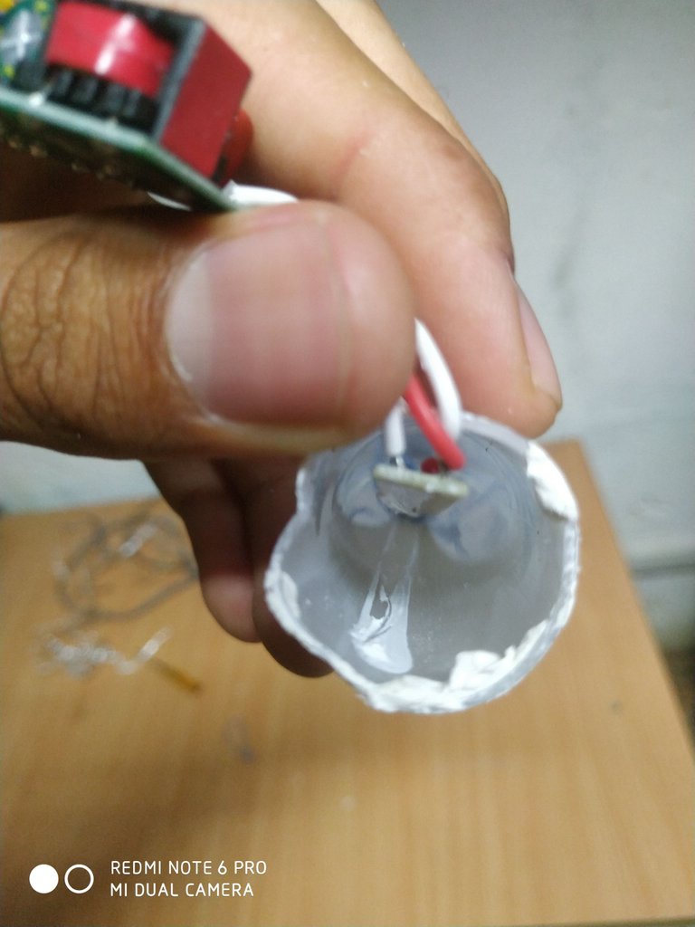
Once the procedure described above was completed, the output of the switched-mode power supply was soldered to the input of the first section of LED strips, isolated inside a piece of plastic tubing to avoid a short circuit against the metal body of the base, and secured with silicone to the back of the base as shown in the following images.
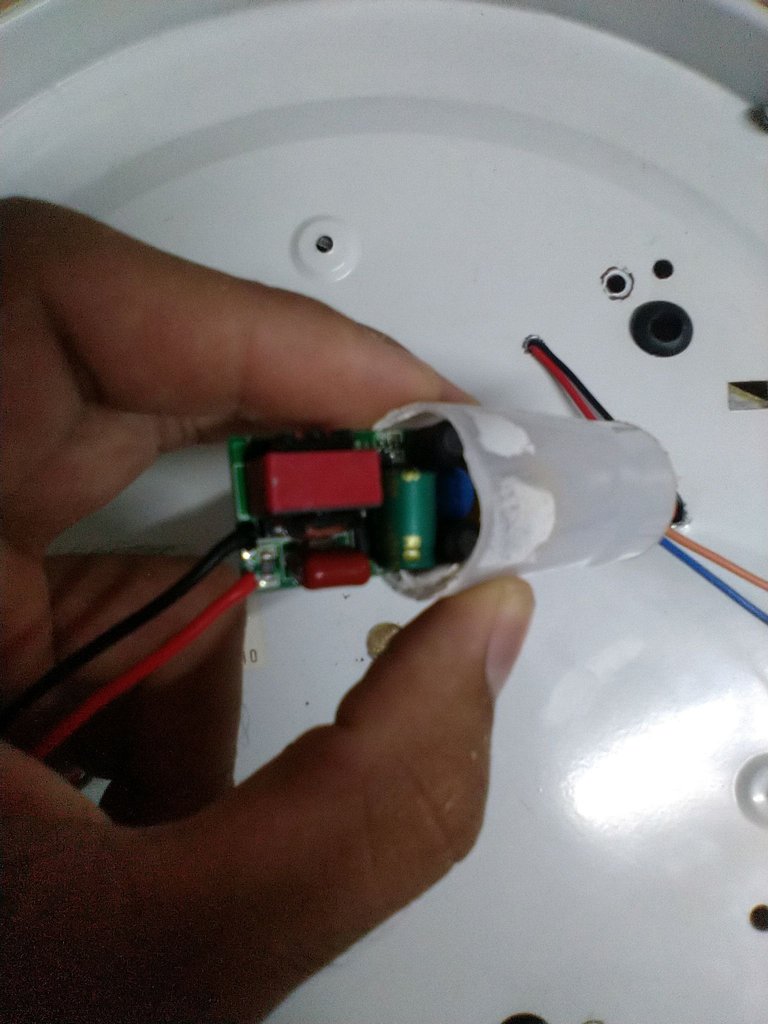
Piece of plastic tube to insulate the switched-mode power supply.
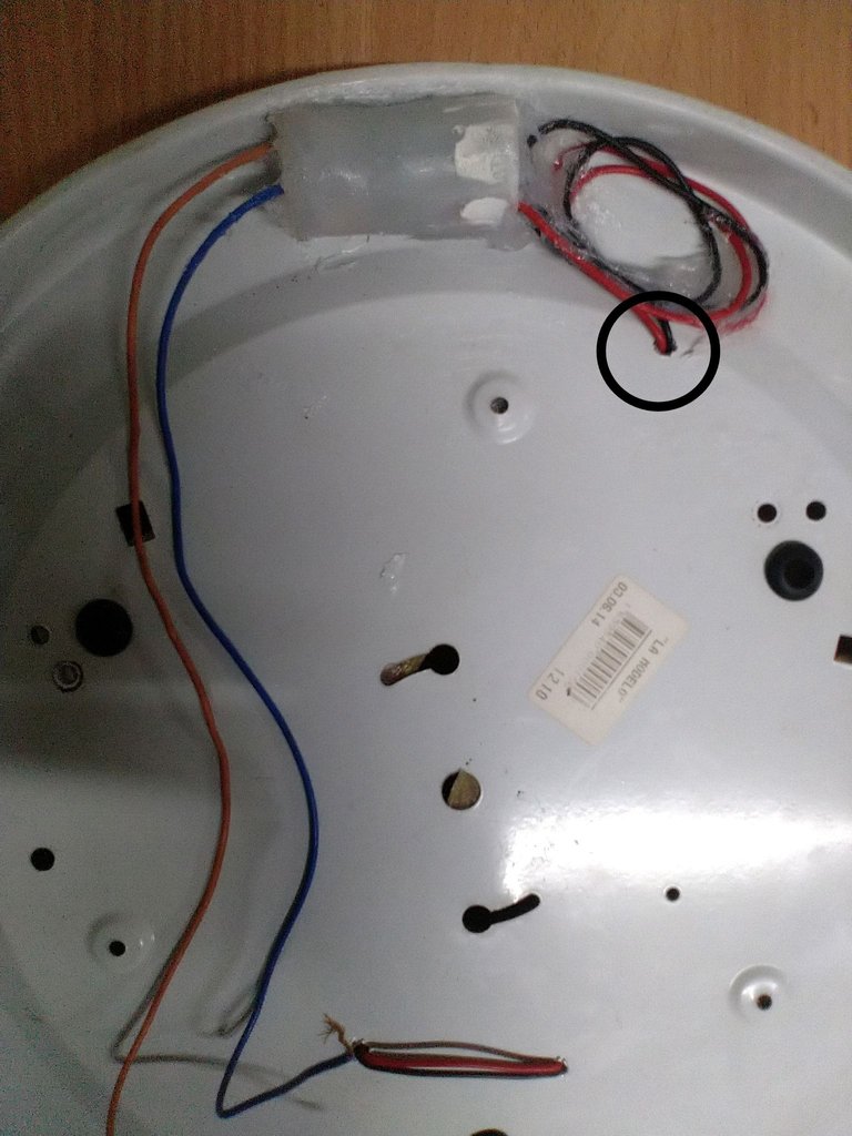
Switched source inside the insulator attached with silicone to the back of the lamp base, the black circle marks the point where the wires that were soldered to the input of the first section of the LED strip enter.
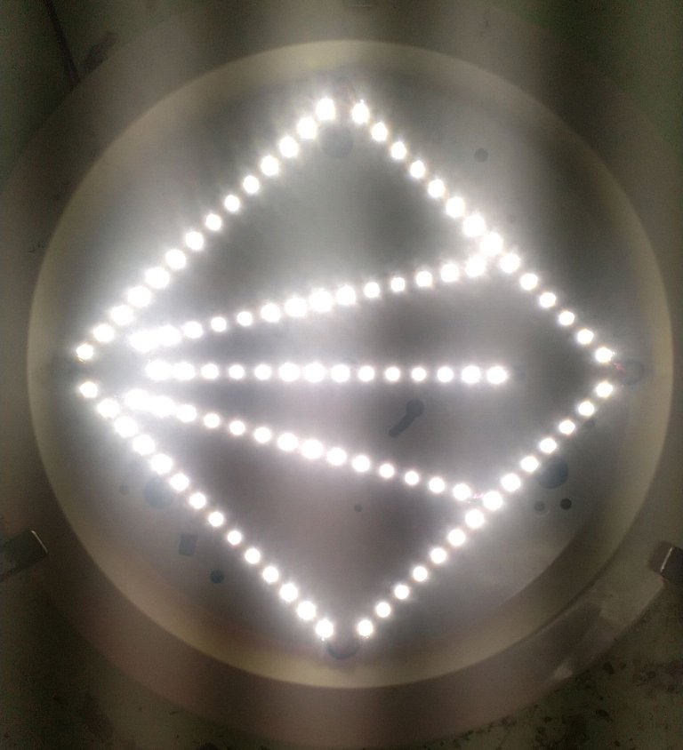
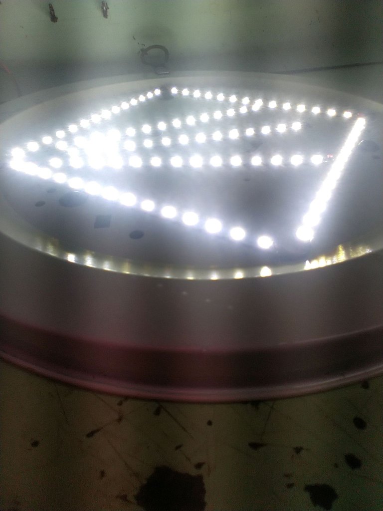
Time to test the lamp 😁.
It was connected to the 110 volt socket and this was the result....
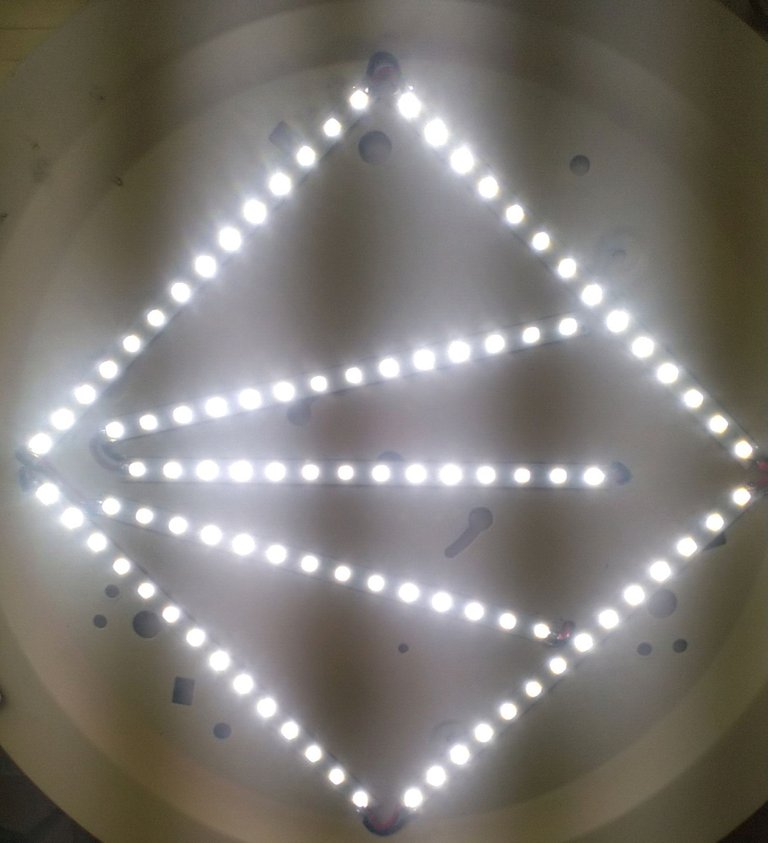
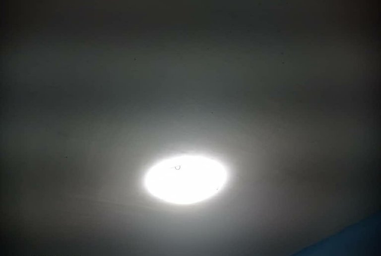
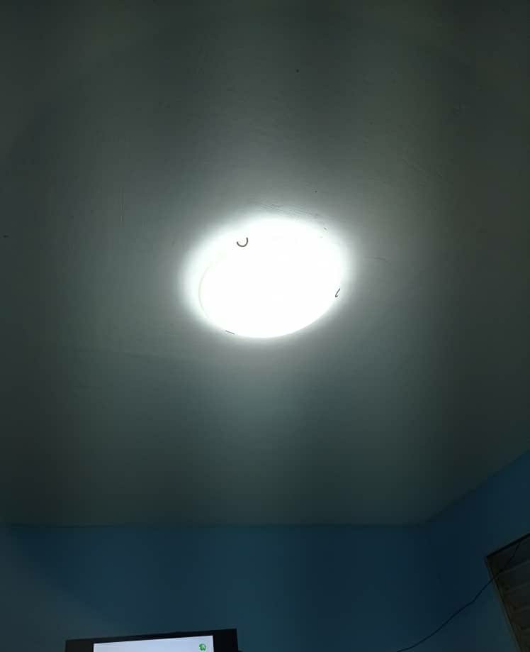
And here I show you how it is already connected and functional in the living room of the house.
In this way I managed to solve a problem using recycled materials. If you liked this work, let me know in the comments, greetings to the whole community.
See you next post😉
Images were taken with my Xiaomi Redmi Note 6 Pro cell phone.
Images edited in the "Gallery" application of the phone and the application Photo Collage-GridArt..
Text translated to English in Deepl translator.
You can see me on Facebook

ESPAÑOL
Saludos a la comunidad. Les contaré que en el techo de la sala de mi casa tengo una de esas lámparas bonitas de cristal que ademas de su función de iluminación, también adornan el entorno, pero recientemente, el último de los tres bombillos incandescentes con los que trabaja dejo de funcionar, por lo que se me creó una problemática ya que no tenia repuestos para sustituir y dejarla funcional.
Sin embargo sí contaba con un tubo LED de 18 watt, pero no quería quitar la lámpara de cristal pues dejaria de adornar la sala , dándome la tarea de hacerle una adaptación con los materiales que tengo en casa, cuyo proceso le describo a continuación.
Primeramente les diré que materiales tenía a mano, pero pudieran emplease otros, todo depende de lo que puedas tener en casa.
-Tubo LED de 18 watt
-Cables de una vieja toma ATX de 24 pines, de una fuente de computadora.
-Dos metros de cable de red Ethernet.
-Tubo de silicona.
En la siguiente imágen les muestro la base de la lámpara de cristal, sobre la cual trabajaré y agregaré las tiras LED como le describiré mas adelante.
Retiré los soquet para reciclarlos y emplearlo en un futuro donde sea necesario.
Luego desarmé el tubo para extraer la tira LED que contiene en su interior. En este tipo de tubo en particular necesité del uso de una pistola de aire de caliente, pero se puede emplear un secador de pelo u otra herramienta que nos permita ablandar la silicona que fija las tapas de los extremos del tubo LED. En las siguientes imágenes les muestro como al aplicar calor a los extremos pude retirar las tapas con ayuda de un destornillador haciendo palanca, hay que hacerlo con cuidado para no dañar las fuente conmutada que alimenta la tira LED.
Pistola de aire caliente
Aplicando calor en los extremos del tubo
Retirar la tapa con ayuda de un destornillador
Fuente conmutada que alimenta la tira LED
Cortar el cable que une la fuente conmutada a la tapa
Cortar el cable del otro extremo que une la tapa
Luego de retirar las tapas, fue necesario extraer la tira LED la cual también estaba adherida con silicona al cuerpo del tubo. Para extraerla sin provocarle daño ultilicé uno de los cables finos que contiene el cable de red Ethernet en su interior. Realicé un lazo en una punta del cable e introduje la otra punta por el interior del tubo hasta que saliera por el extremo opuesto. Luego con el lazo se rodea la punta de la tira LED, para luego tirar del extremo opuesto del cable y así separar la tira LED del cuerpo del tubo sin dañarla.
Cable fino para despegar la tira LED
Lazo en un extremo del cable
Introducir la punta opuesta al lazo del cable por un extremo del tubo
Punta del cable en el extremo opuesto del tubo
Lazo colocado en la punta de la tira LED, quedando entre ella y el cuerpo del tubo
Lazo mientras se tira del extremo opuesto del cable
Imagen durante la extracción de la tira, desde otro ángulo
Extracción de la tira una vez despegada completamente del cuerpo del tubo
Después de extraer la tira LED, la dividí en siete partes iguales, con el objetivo de distribuirla en el cuerpo de la base de la lámpara de cristal.
Una vez hechas las divisiones en la tira, las identifiqué en orden consecutivo para después unirlas nuevamente a través de unos puentes utilizando los cables de la toma ATX de 24 pines.
La unión la realice en cada punto dónde interrumpí la conexión de cobre en la propia tira. A continuación lo muestro en las siguientes fotos para una mejor comprensión.
Puntos en la tira LED dónde le quité la pintura aislante que protege la conexión de cobre, quedando marcada para dividirla en siete partes iguales
Corte de la tira en cada marca
Luego de haber divido las tiras, las superpuse en la base de la lámpara
Una vez superpuesta cada sección se le aplica silicona con el objetivo de fijarlas a la base, y que el calor generado por el consumo de los diodos LED sea disipado por dicha base.
Acá se representan las tiras en orden consecutivo adheridas con silicona y los puntos señalados dónde se harán los puentes para cerrar el circuito de la misma forma en la que estaban conectadas antes de dividirlas
Con ayuda de un soldador cautín se le aplica estaño con cuidado al cobre descubierto en las tiras, evitando unir la conexión negativa con la conexión positiva
Cautín empleado con temperatura en 350 °C y primer puente realizado, señalado en el círculo negro
Todos los puentes culminados, la flecha negra representa el punto por dónde ingresa el voltaje de directa proveniente de la fuente conmutada, y el resto de las flechas representa el orden en el que van unidas las tiras.
Fuente conmutada a la que se le soldaron los cables de entrada de corriente alterna (azul y naranja) y los cables de salida de corriente directa ( rojo y negro)
Una vez concluido todo el procedimiento descrito anteriormente se soldó la salida de la fuente conmutada a la entrada de la primera sección de tiras LED, se aisló dentro de un trozo de tubo plástico para evitar un cortocircuito contra el cuerpo metálico de la base, y se fijó con silicona al reverso de la base como se observa en las siguientes imágenes.
Trozo de tubo plástico para aislar la fuente conmutada
Fuente conmutada dentro del aislante fijada con silicona al reverso de la base de la lámpara, el círculo en negro señala el punto por dónde entran los cables que se soldaron a la entrada de la primera sección de la tira LED.
Hora de probar la lámpara 😁
Se conectó a la toma de 110 volt y este fue el resultado...
Y acá les muestro como quedó ya conectada y funcional en la sala de la casa.
De esta forma logré resolver una problemática utilizando materiales reciclados. Si te ha gustado este trabajo, déjamelo dicho en los comentarios, un saludo para toda la comunidad.
Hasta el próximo post😉.
Las imágenes fueron tomadas con mi celular Xiaomi Redmi Note 6 Pro.
Imágenes editadas en la aplicación "Galería" del teléfono y la aplicación Foto Collage-GridArt.
Puedes verme en Facebook

Bienvenido a la comunidad, me gusto mucho tu trabajo aprovechando todos estos materiales para optimizarlos, muy adecuado en este tiempo de crisis. Excelente resultado final amigo. Felicidades y éxitos @darknapol ✨
!DIY
Gracias por comentar amiga, y me alegro que te haya gustado, es un placer entrar a la comunidad a dar mis pequeños aportes y aprender de los suyos. Es muy buena la ideología del reciclaje y más aún como dices tú, en estos tiempos difíciles, además de la satisfacción de hacer con nuestras propias manos nuestros trabajos o reparaciones para mejorar nuestras condiciones de vida, sumado a tener la posibilidad de compartir lo que sabemos con otras personas, particularmente me gusta mucho aprender de los demás, pienso que todos tenemos algo que enseñar y a la vez algo que aprender. El proyecto me sirvió de mucho pues al final tengo más iluminación en la sala que antes de adaptarla. Saludos
https://leofinance.io/threads/dayadam/re-leothreads-35gajcsam
The rewards earned on this comment will go directly to the people ( dayadam ) sharing the post on LeoThreads,LikeTu,dBuzz.
Congratulations!
Your post has been manually curated and reblogged.
You can follow our curation trail on Hive.Vote
If you want to support us and the authors we vote for you can upvote this comment or delegate some Hive Power to our account. Thanks!
Propose a worthy post by mentioning us in the post or in a comment.
We reblog curated posts, follow us if you wish to see them in your feed.
Very good job of recycling, and very useful. Congratulations for the final result. Thank you for sharing this step by step in our community. Welcome // Muy buen trabajo de reciclaje, y muy util. Felicidades por el resultado final. Gracias por compartir este paso a paso en nuestra comunidad. Bienvenido
Thank you, it is a pleasure for me to belong to this beautiful community, I am here to learn from everyone and contribute my grain of sand to everyone. Greetings
You can query your personal balance by
!DIYSTATSThis is pure masterpiece, your recycling job is exceptional.
I really love the final look of the lamp and would have love to have something like this too.
This post has been selected by the Newbies Initiative team and will receive support from the Hive Learners Community. Kindly click on the banner to visit our community and check out our Discord channel here.
If you'll love to know more about the @newbies-hive and how to join, then I'll suggest you go through this post.
Hello greetings. Thank you for commenting, I am pleased that you liked the work, I am one of the people who likes to recycle and solve problems with my own hands and on my imagination , I joined the community to learn from you and contribute my grain of sand. It would be a pleasure for me to be able to help you if you need to do some work like this at home, I will be at your disposal to help you without any problem. Greetings.
This is really impressive job done. Thanks so much.
Thank you friend, it is a pleasure for me to belong to the community, learn from you and contribute my bit. Greetings
Thank you friend, it is a pleasure for me to belong to the community, learn from you and contribute my bit. Greetings
Congratulations @darknapol! You have completed the following achievement on the Hive blockchain And have been rewarded with New badge(s)
Your next target is to reach 100 replies.
You can view your badges on your board and compare yourself to others in the Ranking
If you no longer want to receive notifications, reply to this comment with the word
STOPCheck out our last posts: