
Hello Friends of Hive, a pleasure to be with you presenting topics of interest in science, technology, research and innovation.
Hola Amigos de Hive, un gusto estar con ustedes presentándoles temas de interés de la ciencia, tecnología, investigación e innovación.

The logical states 0 and 1 known for which we are attracted to digital, are representations of physical quantities such as voltage and current, whose units in the International System are Volt (V) and Ampere (A), respectively.
Los estados lógicos 0 y 1 conocidos por los que nos atrae lo digital, son representaciones de magnitudes físicas como el voltaje y la corriente, cuyas unidades en el Sistema Internacional (SI) es el Voltio (V) y el Amperio (A), respectivamente.
To explain the above, we will do a practical exercise based on an integrated circuit containing inverter logic gates or Not, from the logic to the magnitudes that represent the logic states.
Para explicar lo anteriormente señalado, haremos un ejercicio práctico apoyándome en un circuito integrado que contiene compuertas lógicas Inversoras (Not), desde la lógica hasta las magnitudes que representan lo estados lógicos.
Who is the Inverter? /¿Quién es el Inversor?
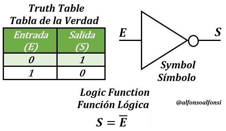
The inverter has a digital input and output. It generates an inverse or opposite output to its input, according to its Truth Table with a logic function and a symbol that represents it in logic circuits, as you can see below.
El inversor tiene una entrada y una salida digital. Genera una salida inversa o contraria a su entrada, según su Tabla de la Verdad con una función lógica y un símbolo que la representa en los circuitos lógicos, como pueden ver a continuación.
Who is 1? and who is 0? / ¿Quién es 1? y ¿quién es 0?
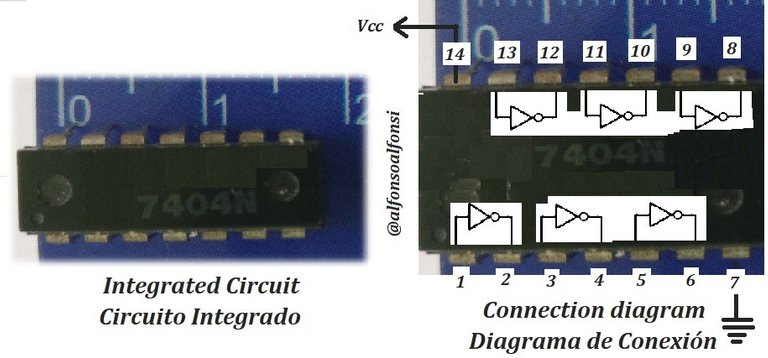
I pointed out that this would be practical, so I take a 7404 integrated circuit containing NOT logic gates and look at its wiring diagrams and electrical characteristics, which are in the datasheet. For example, in Alldatashett, can be consulted.
Señalé que esto sería práctico, así que tomo a un circuito integrado 7404 que contiene compuertas lógicas NOT y vemos sus diagramas de conexión y características eléctricas, que están en las ficha técnica. Por ejemplo, en Alldatashett, pueden consultarla.

From the above table, it can be extracted that for logic 1 the voltage must be between less than or equal to 5.25 V and greater than or equal to 2.00 V. On the other hand, voltages less than or equal to 0.8 V and greater than or equal to 0.00 V will be a logic 0.
De la Tabla anterior se extrae que para un 1 lógico el Voltaje debe estar entre menores e iguales que 5,25 V y mayores o iguales a 2,00 V. Por otro lado, los voltajes menores o iguales a 0,8 V y mayores o iguales a 0,00 V serán un 0 lógico.
There is a range between less than 2 V and greater than 0.8 V that the circuit does not recognize the 0 or 1.
Existe un rango entre menores a 2 V y mayores a 0,8 V que el circuito no reconoce el 0 o el 1.
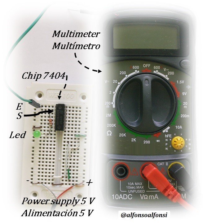
From the above, we make our experience with the assembly on a breadboard and measure the voltage with the multimeter on the E input (pin 1) and S output (pin 2) of the 7404.
De lo anterior, hacemos nuestra experiencia con el montaje en un protoboard y medimos el voltaje con el multímetro en la entrada E (pin 1) y salida S (pin 2) del 7404.
It is worth mentioning that the practical assembly of the experience was carried out with my proprietary equipment and materials. Also, the procedure described for obtaining the results is my own.
Vale la pena destacar, que el montaje práctico de la experiencia lo realicé con equipos y materiales de mi propiedad. Así como también, el procedimiento descrito para la obtención de los resultados es propio.
The measurements are shown below:
Las medidas se muestran a continuación:
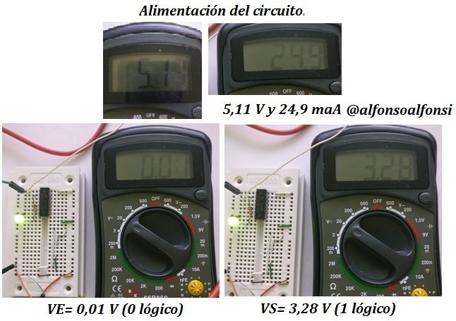
With a logic 0 excitation at the output of the integrated circuit, we have logic 1. In addition, a green LED was placed to signal when this happens.
Con una excitación 0 lógico en la salida del circuito integrado tenemos 1 lógico. Además, se colocó un LED verde para que señalara cuando esto sucediera.
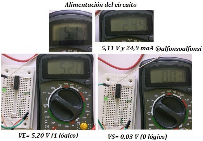
With an input with logic 1, the output is logic 0. The indicator LED is off.
Con una entrada con un 1 lógico la salida es un 0 lógico. El Led indicador está apagado.
The voltage magnitudes are within the range indicated on the datasheet. So, when you are going to assemble a circuit with logic gates, be sure to check the parameters in the circuit datasheet, and then you will not have any surprises.
Las magnitudes de voltaje están dentro del rango que la ficha técnica indica. Así que, cuando vayas a montar un circuito con compuertas lógicas, asegúrate de chequear los parámetros en la ficha técnica del circuito, y así no te llevarás sorpresas.
Well, I also took the opportunity to explain the inverting logic gate or Not.
Bueno, también aproveché de explicar la compuerta lógica inversora o Not.

See you soon, I hope the reading has been enriching.
Nos vemos pronto, espero que la lectura haya sido enriquecedora.
I invite you to visit my posts and follow me @alfonsoalfonsi.
Te invito a visitar mis posts y seguirme en @alfonsoalfonsi.
Thank you for your time and comments.
Gracias por su tiempo y comentarios.

Consultation Documents
Documentos de Consulta

Lacamare, D. (2018). Embedded Systems Architecture: Explore architectural concepts, pragmatic design patterns, and best practices to produce robust systems. Packt Publishing.
Widmer, N., Moss, G. & Tocci, R. (2018). Digital Systems: Principles and Applications (12th ed.). Pearson Education Limited.
Figures and Images
Figuras e Imágenes

The Home or Title image was made by @alfonsoalfonsi using CANVAS with a free image by Pixabay.
La imagen de Inicio o Título fue realizado por @alfonsoalfonsi usando CANVAS con imagen libre de Pixabay.
The other images that appear in the post are property of @alfonsoalfonsi captured with the camera of the One Plus smartphone and edited in Canvas, product of the procedure performed to obtain the results in the practical experience designed by the author.
Las otras imágenes que aparecen en el post son propiedad de @alfonsoalfonsi captadas con la cámara del teléfono inteligente One Plus y editadas en Canvas, producto del procedimiento realizado para la obtención de los resultados en la experiencia práctica diseñada por el autor.
The separator used is my own and is made using CANVAS and an image from PxHere.
El separador son de mi propiedad y está realizado usando CANVAS e imagen de PxHere.

The banner and the photographs on it are my property. Made with Power Point, Paint and the Linerock Investment LTD ToonMe App.
El banner y las fotografías son de mi propiedad. Realizado con Power Point, Paint y Linerock Investment LTD Aplicación ToonMe.
Hola querido @alfonsoalfonsi, excelente tu explicacioón de los estados lógicos 0 y 1 y la ejemplificación utilizando tus equipos para ilustrar con el procedimiento.
Gracias por compartir, y continuar formando en esta area de conocimiento.
Saludos y exitos.
Hola @raizayanez gracias por seguir mis publicaciones. Muchas veces se explica el 0 y 1 lógico, hacemos operaciones y los manipulamos, pero poca veces, nos explican quienes representan a esas magnitudes. El que diseña debe tomar esta consideración. Gracias
The rewards earned on this comment will go directly to the person sharing the post on Twitter as long as they are registered with @poshtoken. Sign up at https://hiveposh.com.
Thanks for your contribution to the STEMsocial community. Feel free to join us on discord to get to know the rest of us!
Please consider delegating to the @stemsocial account (80% of the curation rewards are returned).
Please consider including @stemsocial as a beneficiary to get a stronger support.
Thank you @steemstem for supporting me. We remain in communication.
Your content has been voted as a part of Encouragement program. Keep up the good work!
Use Ecency daily to boost your growth on platform!
Support Ecency
Vote for new Proposal
Delegate HP and earn more
Thank you @ecency for your support. We are moving forward.