[EN] - Choosing a current sensor
I've been away from Hive for a few days because I have a lot of things to do for my master's degree. So, I decided to focus 100% on my academic obligations, because deadlines don't wait.
This past week, I was conducting some tests on a few current measurement methods, such as the Current Transformer and the Hall Effect Sensor.
Well, a literature review was conducted on these sensors, as well as some tests, to collect data and verify which ones are compatible with the demands of our project.
For those who don't know, I'm working on research to detect faults in electric vehicle motors. It all starts with measuring electric current, which is why it's important to choose a good current sensor that can measure accurately and has a good response.
For this bench test, it was necessary to use an oscilloscope with a test probe (to measure voltage directly from the analyzed sensor) and a current clamp (which is our measurement reference). The data is then transferred to the computer where it will be compared and finally used in the fault detection algorithm.

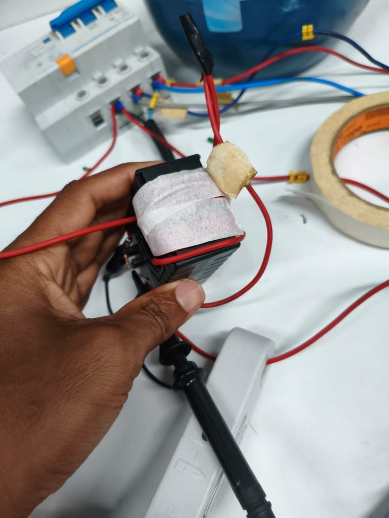
The figure below shows the ASC712 Hall effect sensor, which measures both direct and alternating electric current. The maximum current that this sensor can measure is 30A. The operating principle of this sensor uses a magnetic field. When electric current flows through a conductor, it generates a magnetic field proportional to the current passing through it.
This sensor is basically built with semiconductors, using microelectronics, which allows it to shield itself from external noise in an environment, thus improving measurement. This sensor is invasive, and the circuit must be interrupted if you want to use it for measurement. This is one of the few disadvantages of this sensor.

300/5A current transformer
The figure below shows a current transformer, which uses magnetic flux, which is also proportional to the current passing through it. However, what we have is the derivative of the magnetic flux, which means that the measured signal is not exactly the electric current, but rather the derivative of the current.
The current signal was measured simultaneously with the current clamp and each sensor shown. Initially, the measured current is sent to the computer, where it will be processed in Matlab software, and finally the Root Mean Square Error (RMSE) is calculated.
The figures below show the current signals measured by the current clamp (in red) and the current transformer. If you look closely at the CT signal, you will see that the current signal is different from that measured by the current clamp.

The next figure is just a zoom to facilitate visualization. The alternating current or voltage signal returns a sine wave, but the current transformer cannot make this measurement at motor start-up because the current is derived from the magnetic flux, so we have the derivative of the current at the output.

The image below shows a comparison of the frequency components for each measurement method. The frequency spectrum for the current clamp (gold standard) is shown in red, and the signal measured by the CT is shown in blue. It can be seen that the frequency components in the CT have lower amplitudes and therefore cannot follow the reference signal.

Even so, passing this signal through the fault detection algorithm shows that it can deliver qualitative fault results, which are the two peaks in the graph on the right. Red refers to current clamp and blue to CT.

The current transformer was not a good candidate for measuring low currents, as this 300/A CT measures well in the range of 200 to 300A. The current of electric vehicle motors is in this range, so we decided to test this possibility.
ASC712 Hall Effect Sensor

The same experiment was performed for the 30A ASC712 Hall effect sensor. The currents were measured and compared, returning a mean square error of 0.2327. The current signal from the Hall effect sensor closely follows the reference signal.

For this reason, it also behaves in the same way as a current clamp in the frequency spectrum. Therefore, the results of the fault detection algorithm will be analogous.


Therefore, the Hall effect sensor has proven to be a more efficient method for measuring current in electric vehicles. It is important to note that there are other similar models that can measure currents of up to 200A.
Thank you for reading!

[PT] - Escolha do sensor de corrente
Faz alguns dias que ando sumido da Hive, pois estou com muitas coisas pendentes no mestrado. Então, resolvi focar 100% em minhas obrigações acadêmicas, pois os prazos não esperam.
Essa semana que passou estava realizando alguns teste em alguns métodos de medição de corrente, como Transformador de Corrente e o Sensor de efeito Hall.
Pois, bem foi feita uma revisão bibliográfica a respeito desses sensores, como também alguns testes, para coletar dados e verificar quais deles são compatíveis com a demanda de nosso projeto.
Para quem não sabe estou trabalhando em uma pesquisa para detecção de falhas em motores de veículos elétricos. E tudo começa na medição de corrente elétrica, por isso a importância de escolher um bom sensor de corrente, que consiga medir com precisão e tenha uma boa resposta.
Para esse teste em bancada foi preciso utilizar um osciloscópio com uma ponteira de prova (para medir tensão diretamente do sensor analisado) e um garra de corrente (que é nossa referência de medição ). Depois os dados são passado para o computador onde serão comparados, e por fim utilizado no algoritmo de detecção de falhas.
Na figura abaixo temos o sensor de efeito Hall ASC712, que medi corrente elétrica tanto continua quanto alternada. A corrente máxima que esse sensor consegue medir é de 30A. O principio de funcionamento desse sensor utiliza o campo magnético, quando a corrente elétrica percorre um condutor ela gera campo magnético proporciona a corrente que passa.
Esse sensor basicamente é construído em semicondutor, através da microeletrônica, isso permite que ele consiga se blinda dos ruídos externos em um ambiente melhorando assim a medição. Esse sensor é do tipo invasivo e é preciso interromper o circuito que se desejar medida para utilizá-lo. Essa é uma das poucas desvantagens desse sensor.
Transformador de corrente 300/5A
Na figura abaixo temos um transformador de corrente, que utiliza o fluxo magnético, que também é proporcional a corrente que passa. Porém, o que temos é a derivada do fluxo magnético que faz com que o sinal medido não seja exatamente a corrente elétrica e sim a derivada da corrente.
O sinal de corrente foi medido de forma simultânea com a garra de corrente e com cada sensores apresentado. Inicialmente, a corrente medida é passada para o computador, onde será tratada no software matlab, por fim é calculado o Erro Quadrático Médio (RMSE).
Nas figuras abaixo são apresentados o sinais de correntes medidos pela Garra de Corrente (em vermelho) e para Transformador de corrente. Se observar atentamente para o sinal do TC vai observa que o sinal de corrente é diferente do medido pela Garra de Corrente.
A próxima figura é apenas um zoom para facilitar a visualização. O sinal de corrente ou tensão alternado retorna um senoide, mas o Transformador de corrente não consegue fazer essa medição na partida do motor, porque a corrente apresenta é a derivada do fluxo magnético, então termos na saída a derivada da corrente.
Na imagem abaixo temos um comparativo das componentes de frequência, para cada método de medição. Em vermelho é o espectro de frequência para a garra de corrente (padrão ouro) e o sinal em azul é o espectro para o sinal de corrente medido pelo TC. É possível ver que no TC as componente de frequência tem amplitude menores e por isso não consegue seguir o sinal de referência.
Mesmo assim, passando esse sinal no algoritmo de detecção de falhas é possível ver que ele consegue entregar os resultados qualitativo da falha, que são os dois pico no gráfico a direita. O vermelho refere-se a Garra de corrente corrente e azul ao TC.
O Transformador de corrente não foi um bom candidato para medição de corrente baixas, pois esse TC 300/A medi bem na faixa de 200 a 300A. A corrente do motor de veiculo elétrico são nessa faixa, pois optamos em testa essa possibilidade.
Sensor ASC712 Efeito Hall
O mesmo experimento foi feito para o sensor de efeito Hall ASC712 de 30A. As corrente foram medidas e comparadas, onde foi retornado um erro quadrático médio de 0.2327. O sinal de corrente do sensor de efeito Hall consegue seguir bem o sinal de referência.
Por este motivo no espectro de frequência ele também possui o mesmo comportamento da garra de corrente. Então, o resultado do algoritmo de detecção de falhas serão análogos.
Portanto, o sensor de efeito Hall se mostro um método mais eficiente para medições de corrente, em veículos elétricos. É importante frisar que há outros modelos semelhantes mais que conseguem medir corrente de até 200A.
Obrigado por chegar até aqui!
Posted Using INLEO
Obrigado por promover a comunidade Hive-BR em suas postagens.
Vamos seguir fortalecendo a Hive
Thanks for your contribution to the STEMsocial community. Feel free to join us on discord to get to know the rest of us!
Please consider delegating to the @stemsocial account (85% of the curation rewards are returned).
Consider setting @stemsocial as a beneficiary of this post's rewards if you would like to support the community and contribute to its mission of promoting science and education on Hive.
Very educative post, great work.
!ALIVE
this so interesting i really love technologies ang sciences