We have already introduced the brushless motor in the blog in a theoretical way, understanding the principle of operation we can design some control circuits according to our needs (or just buy an ESC if you are not an expert in the field).
Some circuits with only 3 mosfets, some diodes and resistors seem to be enough to make them turn, however my goal is an automatic control in which we do not need to turn a potentiometer or set the speed manually but that this responds automatically to certain sensors or input signals.
With this in mind I have thought about the simplest way to control a brushless motor using the PIC18F2550 as a controller, the simplest result has been through a half bridge system that I will explain below.
Ya hemos introducido el motor brushless en el blog en forma teórica, entendiendo el principio de funcionamiento podemos diseñar algunos circuitos de control según nuestras necesidades (o simplemente comprar un ESC si no eres experto en la materia)
Algunos circuitos con solo 3 mosfets, algunos diodos y resistencias parecen valer para hacerlos girar, sin embargo mi objetivo es un control automático en el que no necesitemos girar un potenciómetro o establecer la velocidad de forma manual sino que este responda de forma automática a ciertos sensores o señales de entrada.
Con esto en mente he pensado en la forma más sencilla de controlar un motor brushless usando el PIC18F2550 como controlador, el resultado más simple ha sido mediante un sistema de medio puente que explicaré a continuación.
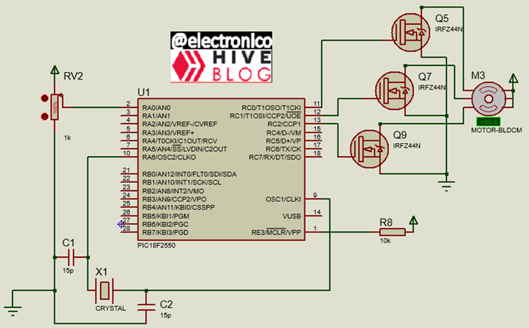
Let's think for a moment about a brushless motor whose stator is made up of 3 coils connected in star configuration, the stator is made up of magnets, each magnet with its two respective poles.
When a coil is energized it creates an electromagnetic field, the magnet will respond to this electromagnetic field according to the polarity closest to it and this response will create a mechanical movement since the magnets are in the rotor which will move by the attraction/repulsion to the electromagnetic field created.
Pensemos por un momento en un motor brushless cuyo estator está conformado por 3 bobinas conectadas en configuración estrella, el estator está conformado por imanes, cada imán con sus dos polos respectivos.
Cuando se energiza una bobina esta crea un campo electromagnético, el imán responderá a este campo electromagnético según sea la polaridad más cercana al mismo y esta respuesta creará un movimiento mecánico ya que los imanes están en el rotor este se moverá por la atracción/repulsión al campo electromagnético creado.
 Буряк Артём Wikimedia Commons
As can be noticed, making a brushless motor rotate is not as simple as connecting a DC power supply, at this point it is important to note that the impedance of each coil is small, this implies that the time by which they are energized must be very small to avoid damage.
Having said the above we can assume that activation and deactivation is required sequentially to produce the rotation in the desired direction, for this it is important to identify each of the coils and then send the pulses in the correct order. It may sound a bit complicated but once you practice it becomes easier.
To activate a coil can be enough a mosfet transistor, but besides considering the time during which the coil is kept energized it is important to implement some protection circuits both to the mosfet and to the microcontroller.
Como se puede notar, hacer girar un motor brushless no es tan simple como conectar una alimentación DC, en este punto es importante resaltar que la impedancia de cada bobina es pequeña, esto implica que el tiempo mediante el cual se energizan debe ser muy pequeño para evitar que se dañen.
Dicho la anterior podemos asumir que se requiere una activación y desactivación en forma secuencial para que se produzca el giro en el sentido deseado, para esto es importante identificar cada una de las bobinas y luego de esto enviar los pulsos en el orden correcto. Puede sonar algo complicado pero una vez que lo practicas se vuelve más sencillo.
Para activar una bobina puede ser suficiente un transistor mosfet, pero además de considerar el tiempo mediante el cual se mantiene la bobina energizada es importante implementar algunos circuitos de protección tanto al mosfet como al microcontrolador.

I like to exaggerate the protections in my circuits, I prefer to add an unnecessary cheap component (like a diode) than to lose a component as important as a microcontroller 😄.
In the circuit shown we have a microcontroller, the brushless motor and a mosfet connected to one of the coils, the other two mosfets will have similar circuits so explaining one is enough, the added components (resistors and diodes) fulfill the following protection functions:
R10 limits the output current of the microcontroller, since 5VDC is provided the current will depend on the load and cannot be higher than 20mA to avoid damaging the microcontroller, to ensure that the maximum allowed value will not be reached or exceeded we add a safety resistor that will limit the output current to values lower than 20mA.
D7: Protects the microcontroller from reverse currents, since the diode is in reverse bias prevents negative peaks or negative voltages that may come from the coils or mosfet from reaching the microcontroller.
R9: It is necessary so that the mosfet can switch OFF when there is no ON signal present, otherwise small noise signals can keep it activated in the absence of the ON signal (this, in addition to generating an unwanted signal, would damage the motor coil corresponding to the mosfet).
D9 Protects the mosfet from the negative peaks generated by the connection/disconnection of the coil.
D8 Protects the mosfet from the positive voltage peaks that can occur when the coil is energized, these peaks can be so high that they represent a danger to the mosfet.
Me gusta exagerar las protecciones en mis circuitos, prefiero agregar un componente económico innecesario (como un diodo) que perder un componente tan importante como un microcontrolador 😄.
En el circuito mostrado tenemos un microcontrolador, el motor brushless y un mosfet conectado a una de las bobinas, los otros dos mosfets tendrán circuitos similares así que con explicar uno es suficiente, los componentes añadidos (resistencias y diodos) cumplen las siguientes funciones de protección:
- R10 limita la corriente de salida del microcontrolador, ya que se proporcionan 5VDC la corriente dependerá de la carga y no puede ser mayor a 20mA para evitar dañar el microcontrolador, para asegurar que no se llegará o pasará del valor máximo permitido añadimos una resistencia de seguridad que limitará la corriente de salida a valores menores que 20mA.
- D7: Protege al microcontrolador de corrientes inversas, ya que el diodo está en polarización inversa evita que lleguen al microcontrolador los picos negativos o voltajes negativos que puedan venir de las bobinas o mosfet.
- R9: Es necesaria para que el mosfet pueda conmutar a OFF cuando no haya una señal de ON presente ya que de lo contrario pequeñas señales de ruido lo pueden mantener activado en ausencia de la señal ON (esto además de generar una señal indeseada dañaría la bobina del motor correspondiente a dicho mosfet).
- D9 protege al mosfet de los picos negativos generados por la conexión/desconexión de la bobina.
- D8 Protege al mosfet de los picos de voltaje positivo que se pueden producir cuando se energiza la bobina, estos picos pueden ser tan altos que representan un peligro para el mosfet.
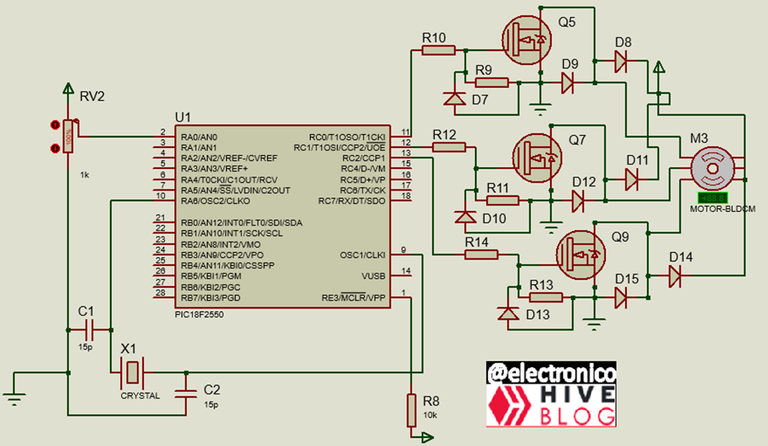
Thus, the half-bridge circuit that we are going to implement including the necessary protections. The most important protection must be included in the programming of the microcontroller which is the time that the coils will remain energized and the sequence in which they are energized. But this is material for the next article.
De esa forma quedaría el circuito de medio puente que vamos a implementar incluyendo las protecciones necesarias. La protección más importante se debe incluir en la programación del microcontrolador que es el tiempo que permanecerán las bobinas energizadas y la secuencia en que se energizan. Pero este es material para el siguiente artículo.
If you want to give an extra boost to the blog with a donation you can send it to the addresses:
Si quieres darle un impulso extra al blog con una donación puedes enviarla a las direcciones:
BEP-20: 0x5Aee5e3e3ED3203e77eF0d8Bb3E3a420E5229Ce0
ERC-20: 0x5Aee5e3e3ED3203e77eF0d8Bb3E3a420E5229Ce0
Arbitrum One: 0x5Aee5e3e3ED3203e77eF0d8Bb3E3a420E5229Ce0
Polygon: 0x5Aee5e3e3ED3203e77eF0d8Bb3E3a420E5229Ce0
Avalanche: 0x5Aee5e3e3ED3203e77eF0d8Bb3E3a420E5229Ce0
Thanks for your contribution to the STEMsocial community. Feel free to join us on discord to get to know the rest of us!
Please consider delegating to the @stemsocial account (85% of the curation rewards are returned).
You may also include @stemsocial as a beneficiary of the rewards of this post to get a stronger support.