Continuing with the theme of DC motor controls today we will use an integrated driver known as H-bridge, this contains the transistor array arranged as described in the previous article on the subject.
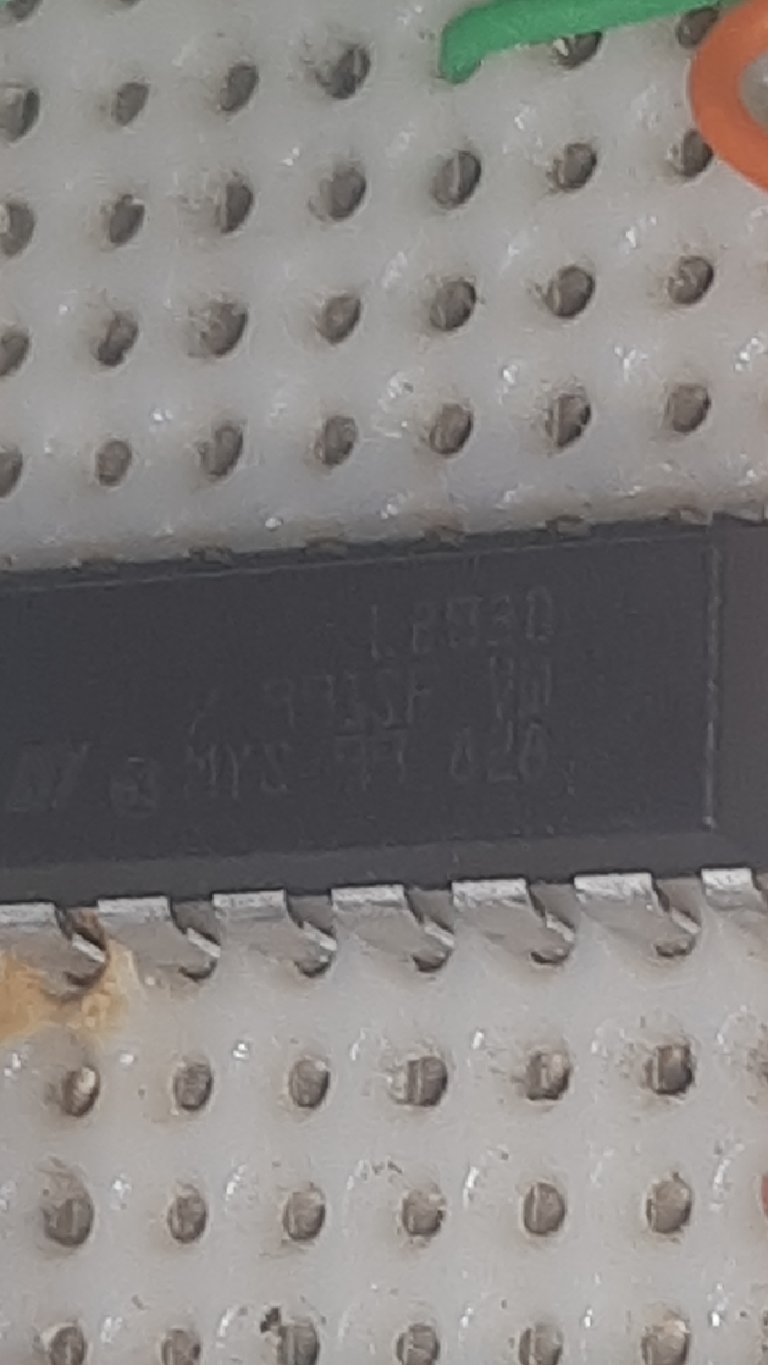
Starting with the challenges proposed for the blog today there will be no simulations but real tests for which it has been necessary to buy an H-bridge and the selected candidate is the L293D model.
Siguiendo con el tema de controles para motores DC el día de hoy utilizaremos un driver integrado que se conoce como Puente H, este contiene el arreglo de transistores dispuestos como se describió en el artículo anterior sobre el tema.
Iniciando con los retos propuestos para el blog hoy no habrán simulaciones sino pruebas reales para lo cual ha sido necesario comprar un puente H y el candidato seleccionado es el modelo L293D.
It is a 16-pin integrated circuit, it is so because inside it has two H-bridges, in other words it can control up to 2 motors under the schemes we have described for rotation control but additionally an additional input is added to each bridge for power control which is very useful for speed control through a PWM signal.
Se trata de un circuito integrado de 16 Pines, es así porque en su interior posee dos puentes H, dicho de otra forma puede controlar hasta 2 motores bajo los esquemas que hemos descrito para control de giro pero adicionalmente se añade una entrada adicional a cada puente para un control de energía que es muy útil para el control de velocidad mediante una señal PWM.
It has two power supply voltages, one for logic control through PIN16 and another for power supply to the motors through PIN8, the logic control responds to the voltage values that change the rotation of the motor while the power supply corresponds to the voltage with which the motors will be energized.
All the configuration on this integrated can be seen in the following image courtesy of Texas Instruments.
Tiene dos voltajes de alimentación, uno para el control lógico mediante el PIN16 y otro para suministro de energía a los motores por el PIN8, el control lógico responde a los valores de voltaje que hacen cambiar el giro del motor mientras que el suministro de energía corresponde al voltaje con el que se van a energizar los motores.
Toda la configuración sobre este integrado la podemos apreciar en la siguiente imágen cortesía de Texas Instruments.
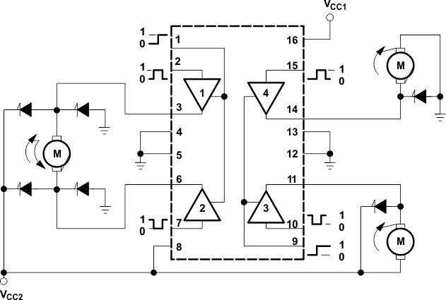 TI Datasheet
Having the H-bridge ready, we only have to introduce the logic signals for the desired direction of rotation and the enable signal for each bridge, which in turn can be replaced by a PWM signal for speed control.
It is here where our PIC18F452 microcontroller takes center stage, by means of which we can program a control logic.
Although in this occasion we will only create a simple program to test the operation of our integrated L293D, which implies that we will send commands manually through the microcontroller, for this we will use two pushbuttons for the direction of rotation and a potentiometer for a PWM signal controlled by ADC.
The schematic diagram would be as follows:
Teniendo el puente H dispuesto solo debemos introducir las señales lógicas para el sentido de giro deseado y la señal de habilitación para cada puente que a su vez puede reemplazarse por una señal PWM para el control de velocidad.
Es aquí donde toma protagonismo nuestro microcontrolador PIC18F452 mediante el cual podemos programar una lógica de control.
Aunque en esta ocasión solo crearemos un programa simple para probar el funcionamiento de nuestro integrado L293D, lo que implica que enviaremos comandos en forma manual a través del microcontrolador, para ello usaremos dos pulsadores para el sentido de giro y un potenciómetro para una señal PWM controlada por ADC.
El diagrama esquemático quedaría de la siguiente forma:
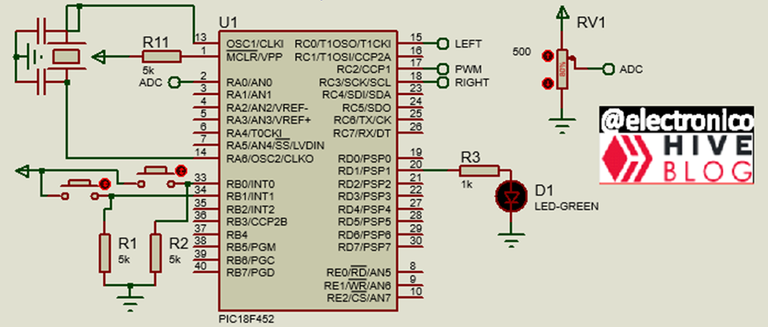
An LED D1 has been placed in PIN20 with the purpose of turning on when the program is running, at first glance it may seem useless but as we are no longer working in simulation is highly recommended in case there are problems in the assembly because it will serve to diagnose if the problem is in the microcontroller or in the rest of the circuit 😉.
In this way our circuit on the breadboard will look like this:
Se ha colocado un LED D1 en el PIN20 con el propósito de que encienda cuando el programa se esté ejecutando, a simple vista puede parecer algo inútil pero como ya no estamos trabajando en simulación es altamente recomendable en caso de que existan problemas en el montaje porque servirá para diagnosticar si el problema está en el microcontrolador o en el resto del circuito. 😉
De esta forma nuestro circuito en la protoboard se verá de la siguiente forma:
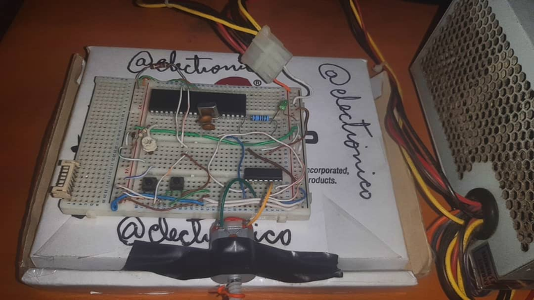
That orange thing that we see in the end of the motor has been a mark that I have put to be able to appreciate the sense of rotation.
Being a program for a manual test it can be done in a simple way with very few lines of code as shown below:
First we set the configuration lines for the PIC18F452, clock frequency and ports to use.
Esa cosa color naranja que vemos en la punta del motor ha sido una marca que he puesto para poder apreciar el sentido de giro.
Al ser un programa para una prueba manual se puede realizar de forma sencilla con muy pocas líneas de código como se muestra a continuación:
Primero establecemos las líneas de configuración para el PIC18F452, frecuencia del reloj y puertos a usar.
#include <18f452.h>

#device ADC = 8

#fuses HS,NOWDT,NOPROTECT,NOPUT,NOLVP,BROWNOUT

#use delay(clock=4M)

#use standard_io(B)

#use standard_io(C)

#use standard_io(D)

#define right          PIN_C0

#define left           PIN_C3
We will only use 3 variables, 2 to capture the state of the pushbuttons and one to capture the ADC value.
Solo usaremos 3 variables, 2 para capturar el estado de los pulsadores y una para capturar el valor del ADC.
int go_right, go_left;

long adc;
Within the main program we configure the CCP1 module for the PWM signal and the ADC on channel 0, we also set the outputs to 0 so that this is their initial state (avoiding surprises 😅).
Dentro del programa principal configuramos el módulo CCP1 para la señal PWM y el ADC en el canal 0, además ponemos a 0 las salidas para que ese sea su estado inicial (evitando sorpresas 😅).
void main()

{

 setup_timer_2(t2_div_by_16, 255, 1);

 setup_ccp1(ccp_pwm);

 setup_adc_ports(AN0);

 setup_adc(adc_clock_internal);

 set_pwm1_duty(0);

 output_c(0x00);

 output_low(PIN_D1);
Now, besides turning on the LED that we use in the PIN20, what we want is to reflect the states of the push buttons (input signals) in the outputs dedicated to control the direction of rotation, we configure the ADC for 8 bits to simply reflect its value in the PWM module that is also 8 bits, in this way the value that we have in the push buttons will be reflected in the outputs for direction of rotation and the value of the ADC will be reflected in the PWM output.
Ahora, además de encender el LED que usamos en el PIN20, lo que queremos es reflejar los estados de los pulsadores (señales de entrada) en las salidas dedicadas a controlar el sentido de giro, configuramos el ADC para 8 bits para simplemente reflejar su valor en el módulo PWM que también es 8 bits, de esta forma el valor que tengamos en los pulsadores se verá reflejado en las salidas para sentido de giro y el valor del ADC será reflejado en la salida PWM.
while(true)

 {

  output_high(PIN_D1);

  set_adc_channel(0);

  delay_us(200);

  adc=read_adc();

  set_pwm1_duty(adc);

  go_right = input_state(PIN_B0);

  go_left = input_state(PIN_B1);

  output_bit(right, go_right);

  output_bit(left, go_left);

  delay_ms(250);
 }
}
Once the program is loaded in the microcontroller we can proceed with the tests, I have separated them into two parts (direction of rotation and speed), because I can only maneuver with one hand taking into account that with the other I hold my phone to record 😅.
Here I have set the PWM to a fixed value and I only have to send signals via the pushbuttons to make the motor rotate in the desired direction.
Una vez cargado el programa en el microcontrolador podemos proceder con las pruebas, las he separado en dos partes (sentido de giro y velocidad), porque solo puedo maniobrar con una mano tomando en cuenta que con la otra sostengo mi teléfono para grabar 😅.
Aquí he fijado el PWM en un valor fijo y sólo tengo que enviar señales mediante los pulsadores para hacer girar el motor en sentido deseado.
For the speed test I put a jumper on one of the pushbuttons to send a fixed signal in the direction of rotation and be able to use my hand to vary the potentiometer which thanks to the programming we did will create a similar variation in the PWM output.
Para la prueba de velocidad he puesto un puente en uno de los pulsadores para enviar una señal fija en el sentido de giro y poder usar mi mano para variar el potenciómetro que gracias a la programación que hicimos creará una variación similar en la salida PWM.
It can be noticed how the speed increases as we move the potentiometer, thus completing the test of the L293D whose responses to the signals of the PIC18F452 microcontroller have been as expected. 😎
See you in the next installment... or in the comments, whichever comes first!
Some of the functions used such as PWM, ADC, Input and Output Handling were not explained because they already had an exclusive article for them, access to those articles I leave them below for those who are not familiar with these topics:
Se puede notar como aumenta la velocidad a medida que movemos el potenciómetro, de esta forma queda completada la prueba del L293D cuyas respuestas a las señales del microcontrolador PIC18F452 han sido las esperadas. 😎
Nos vemos en la siguiente entrega... o en los comentarios, ¡lo que suceda primero!
Algunas de las funciones usadas como PWM, ADC, Manejo de entradas y salidas no se explicaron porque ya tuvieron un artículo exclusivo para ellas, el acceso a dichos artículos los dejo a continuación para quienes no estén familiarizados con estos temas:
- PWM in PIC16F877A EN/ES
- Using ADC in PIC16F877a EN/ES
- Manejo de Salidas en un PIC16F877a usando lenguaje C
- Manejo de Entradas en un PIC16F877a usando lenguaje C
If you want to give an extra boost to the blog with a donation you can send it to the addresses:
Si quieres darle un impulso extra al blog con una donación puedes enviarla a las direcciones:
BEP-20: 0x5Aee5e3e3ED3203e77eF0d8Bb3E3a420E5229Ce0
ERC-20: 0x5Aee5e3e3ED3203e77eF0d8Bb3E3a420E5229Ce0
Arbitrum One: 0x5Aee5e3e3ED3203e77eF0d8Bb3E3a420E5229Ce0
Polygon: 0x5Aee5e3e3ED3203e77eF0d8Bb3E3a420E5229Ce0
Avalanche: 0x5Aee5e3e3ED3203e77eF0d8Bb3E3a420E5229Ce0
Although I do not understand much about electronic installations, I enjoyed reading a lot, as if I were with you during the manufacturing step by step.
Thank you.
Wow, that's really flattering that you enjoyed the article even without understanding it.
But if you continue on that path you will soon have more knowledge on the subject. 😉
Thank you.
Thanks for your contribution to the STEMsocial community. Feel free to join us on discord to get to know the rest of us!
Please consider delegating to the @stemsocial account (85% of the curation rewards are returned).
Thanks for including @stemsocial as a beneficiary, which gives you stronger support.
Thank you!!