LabView software offers pre-designed SubVIs with special functions that can make it much easier for us to create our programs.
These are called Express SubVI and have built-in functions for many engineering fields. Today we will learn how to use an Express SubVI concerning the engineering field we study in this blog, for this I have chosen to simulate signals.
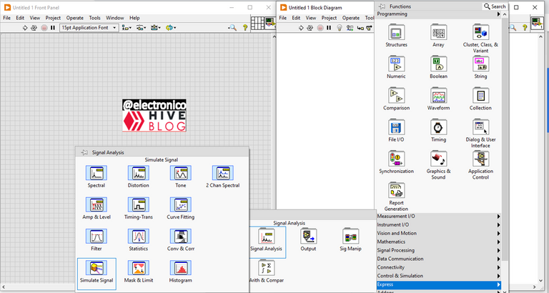
To choose an Express SubVI we just have to right click on the diagram window, scroll to Express and select the one we need.
El software LabView ofrece SubVI prediseñados con funciones especiales que pueden facilitarnos mucho la creación de nuestros programas.
Estos reciben el nombre de Express SubVI y tienen funciones integradas para muchos campos de ingeniería. Hoy aprenderemos a usar un Express SubVI concerniente al campo de ingeniería que estudiamos en este blog, para ello he escogido el de simular señales.
Para elegir un Express SubVI solo debemos hacer click derecho en la ventana de diagramas, hacer scroll hasta donde dice Express y seleccionar el que necesitemos.
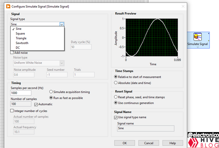
When choosing an express SubVI, a dialog window will open in which we must configure the parameters corresponding to that SubVI.
In our case we have chosen a signal simulator, therefore the parameters to configure will be those corresponding to signals, such as signal type (sinusoidal, triangular, square, sawtooth, DC...), amplitude, frequency, phase, duty cycle (for square wave signal) and even the option to add noise to our signal is present.
Al momento de elegir un express SubVI se abrirá una ventana de diálogo en la cual debemos configurar los parametros correspondientes a ése SubVI.
En nuestro caso hemos escogido un simulador de señales, por lo tanto los parametros a configurar serán los correspondientes a señales, tales como tipo de señal (sinusoidal, triangular, cuadrada, diente de sierra, DC...), amplitud, frecuencia, fase, ciclo de trabajo (para señal de onda cuadrada) e incluso está presente la opción de añadir ruido a nuestra señal.
Once all the parameters have been configured the Express SubVI block will offer terminals to connect controls or constants as required as well as indicators, each according to the appropriate data type.
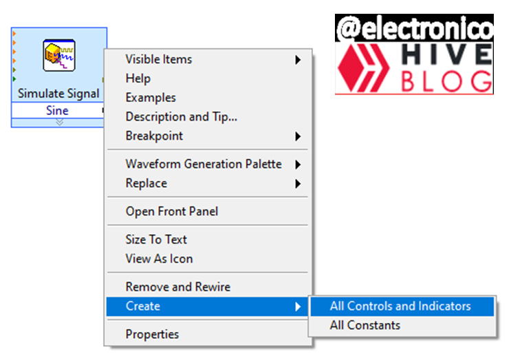
You can create controls, constants and indicators one at a time if the situation warrants it or you can right click on the Express SubVI, look for the create option and select All Controls and Indicators.
This will create all the controls and indicators that the block needs, by the way this can be done with all the blocks in LabView.
Una vez se han configurado todos los parametros el bloque Express SubVI ofrecerá terminales para conectar los controles o constantes segun se requiera asi como tambien los indicadores, cada cosa segun el tipo de datos adecuado.
Se pueden ir creando controles, constantes e indicadores de uno en uno si la situación lo amerita o podemos hacer click derecho en el express SubVI, buscar la opción create y seleccionar All Controls and Indicators.
De esa forma se crearán todos los controles e indicadores que el bloque necesita, por cierto esto se puede hacer con todos los bloques en LabView.

As we can see all the controls and indicators are created including the error cluster, now we proceed to modify them according to our needs, if we need constants where there are controls we change them and so on.
For this case I am not going to modify anything in the block diagram panel (except to put everything in a while structure). But in the front panel to have a better visual of the process.
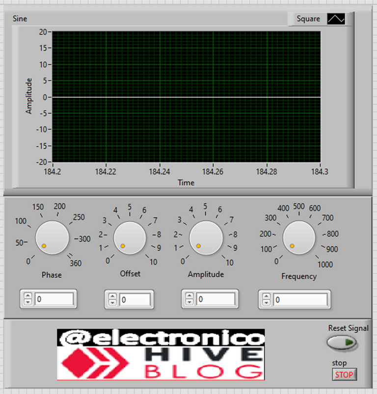
What I do is to hide the error cluster (of the front panel) since I will not do anything with it there for effects of simulating the signal, with respect to the indicators we only have one of the graphical type, what I do is to remove the auto scaling of the Y axis and to put ranges from -20 to 20 for the amplitude.
Regarding the controls what I do is to put knob controls to be able to modify the variables with the mouse in an easy way and I also add a digital control in case you want to enter data with the keyboard, everything else is makeup to improve the appearance.
Como podemos ver se crean todos los controles e indicadores incluyendo el cluster de error, ahora procedemos a modificarlos de acuerdo a nuestras necesidades, si necesitamos constantes donde hay controles los cambiamos y así sucesivamente.
Para este caso yo no voy a modificar nada en el panel diagrama de bloques (salvo poner todo en una estructura while). Pero si en el panel frontal para tener una mejor visual del proceso.
Lo que hago es ocultar el cluster de error (del panel frontal) ya que no haré nada con él ahí para efectos de simular la señal, respecto a los indicadores solo tenemos uno del tipo gráfico, lo que hago es quitar el auto escalado del eje Y y poner rangos de -20 a 20 para la amplitud.
Respecto a los controles lo que hago es poner controles de perillas (knob) para poder modificar las variables con el ratón de forma fácil y añado además un control digital por si se desea introducir datos con el teclado, todo lo demás es maquillaje para mejorar la apariencia.
With all this we are now in conditions to test our express SubVI, but I want that when you look at the simulation you can notice that you can not change the type of signal in hot, that is to say, while the program is running.
It is not very practical to have to stop the execution to change the type of signal to simulate, however it is what the express SubVI offers, but as I particularly like to optimize things we will leave a to be continue... to a next article in which we will learn how to modify an express SubVI to customize it according to our needs 😉.
Without further ado I leave you the simulation hoping that this article can be useful to you, grateful for all the support provided and attentive to the comments section for questions, suggestions and discussions.
Con todo esto ya estamos en condiciones de poner a prueba nuestro express SubVI, pero quiero que cuando mires la simulación puedas notar que no se puede cambiar el tipo de señal en caliente, es decir, mientras el programa está corriendo.
No es muy práctico tener que detener la ejecución para cambiar el tipo de señal a simular, sin embargo es lo que ofrece el express SubVI, pero como a mi particularmente me gusta optimizar las cosas dejaremos un to be continue... a un siguiente artículo en el que aprenderemos a modificar un express SubVI para personalizarlo acorde a nuestras exigencias. 😉.
Sin más os dejo la simulación esperando que este artículo pueda serte útil, agradecido por todo el apoyo brindado y atento a la sección de comentarios para dudas, sugerencias y debates.


Looks quite harder to even try out looking at this picture presentation 🥺
I am very sorry that you find the article difficult to understand. However, I would very much like to make it easier for you to understand, so I would need more details to get to the root of what makes this difficult for you.
Is it just the images?, is it my way of expressing the ideas?, is it your mastery of the subject?, is the whole article incomprehensible to you or just part of it?, if it is just part of it please point out the parts and I will gladly see if something can be done about it.
Thank you very much for your feedback.
I was just scrolling through new posts this morning and landed on this one. I'm not exactly sure what this subVI is but seeing that you post nothing but electronics topics you just got yourself a new follower. I would love to see more people posting stuff like this.
We are surrounded by technology. Instead of throwing it away we could be breaking it down and creating new stuff with it. I want to know more about pcb's and the chips that go on them to make things work. Is there an opensource software that teaches circuits?
Welcome to the blog. Electronics, automation and use of software for such purposes are the main topics here.
I have developed the blog trying that anyone can understand it even if they don't have basic knowledge about electronics, however it has been developed from the fundamental to the complex.
It means that someone with little or no knowledge should start reviewing the older articles of the blog (I think there are not many) in which are explained the basic fundamentals, the use of semiconductor chips and the introduction to the software I use, since each article I write has its fundamental basis in the previous articles and at the same time is the basis for later articles with more complexity.
The article here exposed is nothing more than the explanation of a subprogram called Express SubVI that LabView offers us to simulate the generation of electronic signals and lays the foundation for the next article to develop our own signal simulator.
Regarding an open source software for electronic systems I don't know any, all the ones I manage so far need to buy the license, sorry. But.... anyway if you are interested in learning and decide to consult my previous articles I will be attentive to answer your questions in the comments section for each article.
Once again welcome and thanks for joining.
I will definitely be reading some of the older stuff. I was so interested to learn more about this program I turned to youtube and discovered Industrial IT and automation has a great series on this. This program is pretty neat.
You will discover that LabView is a very interesting program in different areas of engineering, it can be used to create from simple executable programs in windows (.exe) to extensive and complex SCADA systems capable of taking control and automation in industrial processes.
Its ability to communicate is amazing, it can connect with components as unique as microcontrollers to large and robust control systems based on PLCs.
In addition, among many other things, it integrates modules to combine it with other powerful programs such as MatLab and Python, it can create neural network systems, it can be used in the field of robotics and many other interesting areas. The more you discover LabView the more fascinated you will be with it, if you are a lover of automatic systems like me of course.
I would love to see how making a thermometer with an hourly and daily temperature and wind log recording would work using this to program an mmc. 😁😁🤣
Thanks for your contribution to the STEMsocial community. Feel free to join us on discord to get to know the rest of us!
Please consider delegating to the @stemsocial account (85% of the curation rewards are returned).
Thanks for including @stemsocial as a beneficiary, which gives you stronger support.
I think used labview back in 2012 during my PhD rotation. I made a lick sensor and a water release device for mice for an assay in which the mice has to lick for water only on receiving a specific cue. (The idea was to see the multi-signal integration in the brain.) I used labview to sync the three hardware systems - the cue provider, the link sensor, and water release device for both training and detection. I loved the GUI programming. Much easier than the text programming for sure.