It is important to know some optical characteristics of these lenses before describing our exercise, for example, they have two main focuses, one of them called object focus (F), which represents the point where the luminous rays coming from the object are directed to be deflected parallel to the optical axis by the lens, and the image focus (F'), which represents the point where the luminous rays are directed parallel to the optical axis from the object.
Another aspect to consider is the focal length (f) of a lens, if the lens is inside a single material or elastic medium, then, both the object focus (F) and the image focus (F'), will be at the same distance from the lens, only, on opposite sides, there are lenses that are classified in relation to how they refract light rays and, according to these characteristics can be; convergent or divergent, this time we will relate to convergent thin lenses.
When we relate to convergent or positive lenses, we have to visualize those lenses that are thicker in the center than at its ends and, in addition, its object focus (F) will be on the side of the emission of light rays or incidence and the image focus (F') on the other side of the lens, that is, on the side of the transmission of these light rays and transporters of the image of the object analyzed.
Extending the characteristics of converging lenses, we can say that, if the object of analysis is at a greater distance than that represented by the focal length, then we will have the generation of a real image and, therefore, inverted and located on the side of the transmission of light rays, if on the contrary, the object is at a smaller or equal distance, then the image generated would be virtual and, therefore, right, but located on the side of incidence of light rays.
To get a better understanding of the above, you can visualize the following figure 1, and thus be able to notice the scheme of light rays from one side and the other of a converging lens.
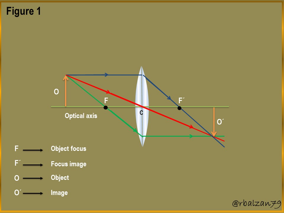
In the previous figure 1, you could notice the action of three luminous rays starting from the object to be analyzed, the blue ray goes parallel to the optical axis and when refracted it passes through the image focus (F'), the red ray passes through the center of the thin lens without deviating or refracting and the third ray (green) passes through the object focus and when it hits the lens it refracts parallel to the optical axis, with these rays it is possible to know the formation of the image on the other side of the lens, and even with the implementation of two rays we could achieve our goal of being able to find the place of generation of the image on the side of the transmission of these rays of light, therefore, in relation to all of the above, we can perform the approach of our exercise of a convergent lens.
Exercise
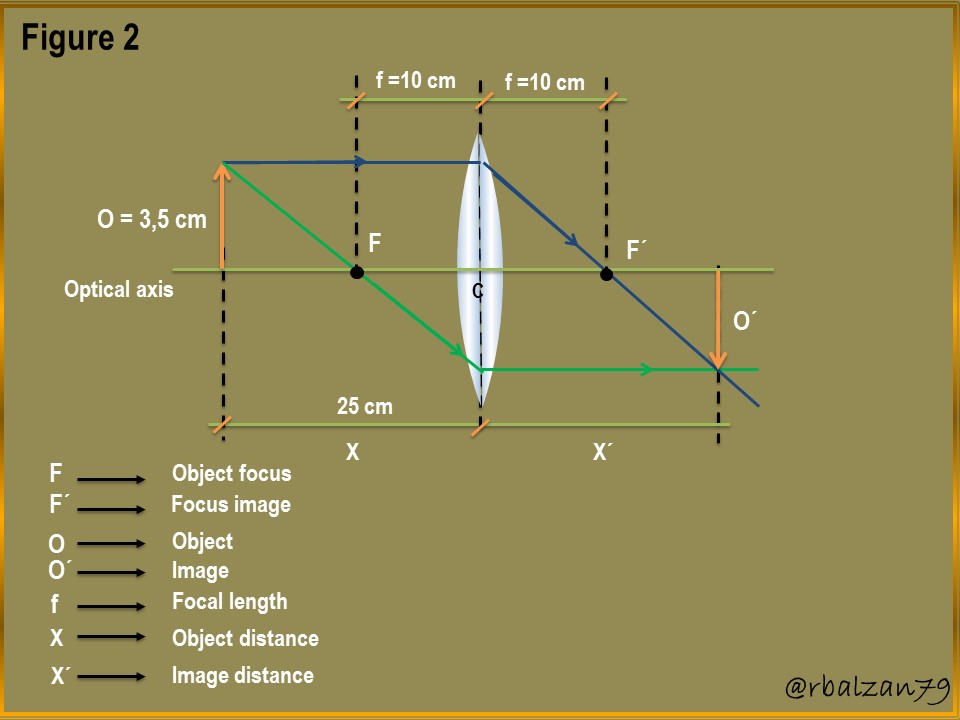
In order to analyze the generation of an image in a thin convergent lens, we decided to place an object at a distance of 25 cm from the convergent lens, the height of the object is 3.5 cm and the focal length of this optical system is 10 cm, in relation to the above, answer the following questions:
a.- What will be the distance of the image with respect to the converging lens?
b.- What will be the size of the image?
b.- What will be the power of the lens?
Solución
Data:
Y = 3,5 cm (Object height).
X = 25 cm (Object distance).
f = 10 cm (Focal length).
X´= ? (Distance of the image with respect to the converging lens).
Y´= ? (Image height).
P =? (Lens power).
Before performing the calculations, it is necessary to express the sign conventions for the whole process of image generation, where X represents the distance of the object with respect to the converging lens, and it will be positive when the object is on the incidence side of the light rays, and negative if the object is on the transmission side of the light rays.
In the case of X' it represents the distance of the lens image, which will be positive if the image is generated on the transmission side of the light rays, therefore, it will be real, and it will be negative and thus virtual if it is generated on the incidence side of the light rays, for focal lengths in converging lenses this value will be positive.
a.- To begin to answer our first question we must look at our figure 2, that is, the ray diagram which we have made using two light rays emitted by the object under analysis, and with it, we will also use the equation of the thin lens in order to find the position of the image generated by refracting the light rays.
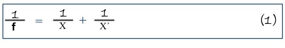
From this formulation, substituting the values we know, we can then clear the requested variable (X') which represents the distance where the image has been generated once the luminous rays have been refracted by the convergent lens, therefore, we have:
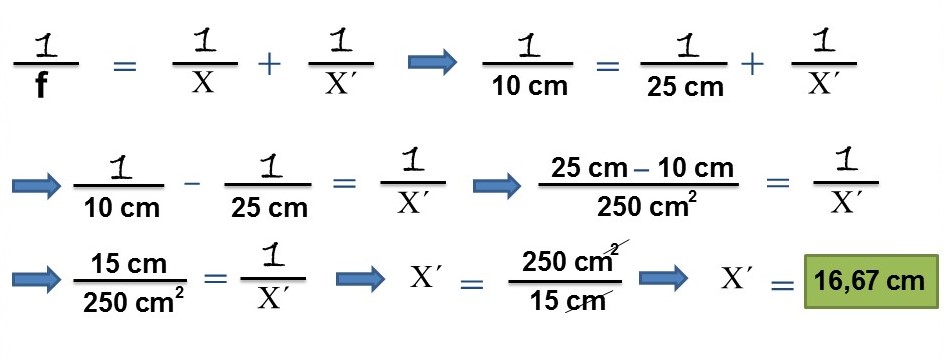
In this way we were able to obtain the position of the image which was formed at a distance of 16.67 cm, being a positive value, it means that the image was generated next to the transmission of light rays once refracted by the convergent lens, so it is real.
b.- In order to answer this second question, we will use the following formulation of lateral magnification.
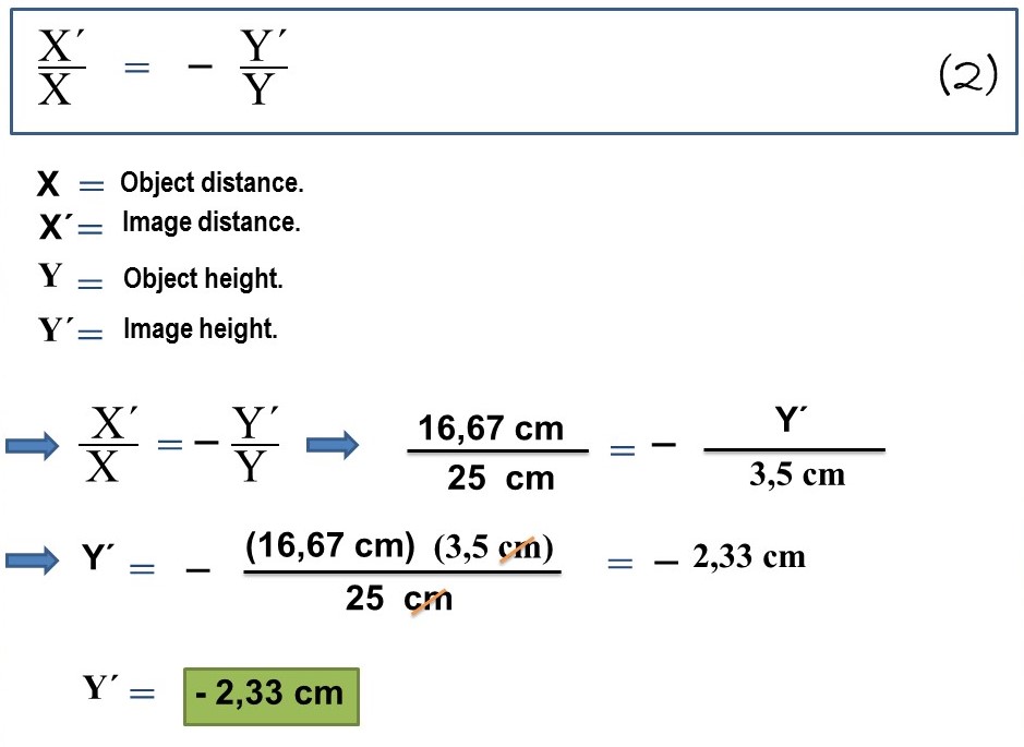
In this way we can calculate the size of the generated image and, in addition, since it is negative, it indicates that it is inverted, characteristic of a real image.
c.- To finish answering our third question, we will use the following lens power formula:
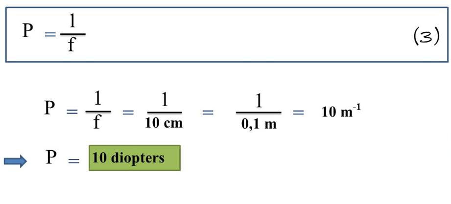
From the above formulation we can highlight that the power (P) of a lens is the inverse of its focal length (f) and, thus, we obtained that the power of the converging lens was 10 diopters.
Conclusion
Artificial lenses play an important or essential role in the life of mankind, with them we have been able to correct any type of visual anomaly, and this thanks to the understanding of the generation of images at the time of refraction of light rays passing through these lenses, in this case convergent.
An interesting journey in the resolution of our exercise, where we managed to structure a scheme of the light rays to visualize the image, which turned out to be real, since it was formed on the other side of the lens, that is, on the side of the transmission of these light rays, in addition, we calculated the distance of the image with its size and, having a negative sign indicates that it is inverted, characteristic of real images and also smaller than the real object.
Despite the interesting variables mentioned above, we also managed to know the power (P) of the convergent lens, which turned out to be 10 diopters, thus we continue to analyze the propagation of any beam of light rays that carry images, in this case, through a convergent lens immersed in the same material or elastic medium such as air.
Until another opportunity my dear friends.
Note: The images were created by the author using Power Point and Paint, the animated gif using PhotoScape.
Recommended bibliographic references
[1] GEOMETRIC OPTICS. Link.
[2] Convergent lenses. Link..
Thanks for your contribution to the STEMsocial community. Feel free to join us on discord to get to know the rest of us!
Please consider delegating to the @stemsocial account (85% of the curation rewards are returned).
You may also include @stemsocial as a beneficiary of the rewards of this post to get a stronger support.
Thank you for your valuable support, dear community.