Hello there. I have a new drive in me to learn how electronics work. I imagine if you're reading this you have a similar drive in you. I grew up relatively uninterested in how electronics work. But now as I get a bit more knowledge under my belt I see how practical it is to know the basics of electronics. From being able to repair household items to creating your own circuit, it becomes a very handy tool to have in your arsenal of knowledge. There are times when knowing which end of the soldering iron to grab can save you some money. Lately, the enjoyment I've been getting out of electronics is puzzling out how a circuit works and why it does what it does. What the different components do and how they interact with each other. Before we begin, I must admit, I'm still not the best at that. Often I still don't know why the magic black chip does what it does and even reading about it can be above my knowledge level. But I find that doesn't spoil my fun factor at all. I would go so far as to say it enhances it because it leads me down rabbit holes of weird information. If you're a veteran of electronics this post will probably bore you, but please skim it and share some of your tips with me if you notice mistakes, misconceptions, or errors.
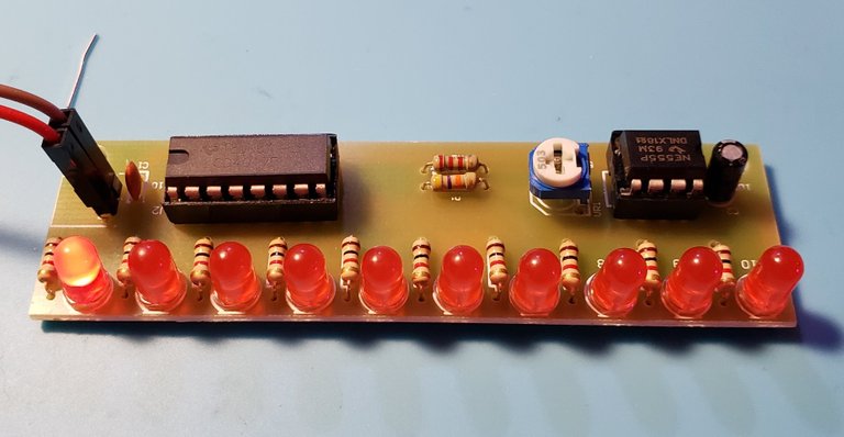
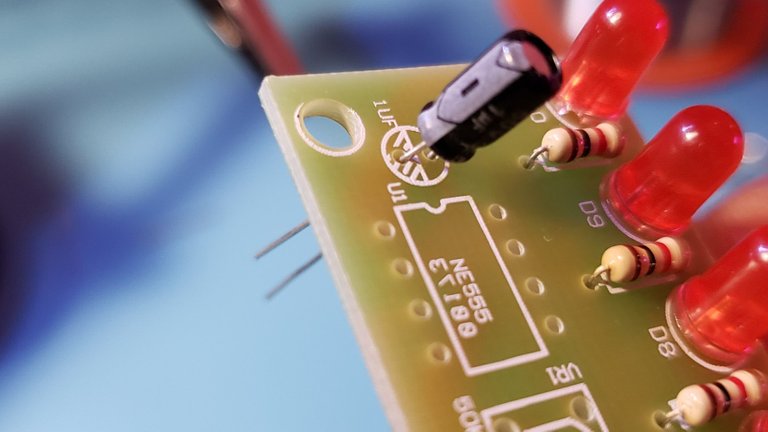
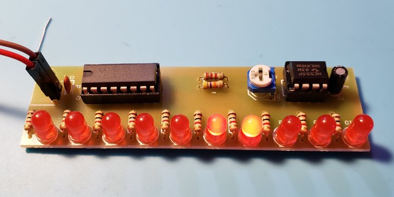
Before we begin, here is the completed module. The 8-pin NE555 timer integrated circuit (ic) acts as a clock for the 16-pin CD4017 step counter ic. The clock speed of the 555 timer is controlled by the white and blue potentiometer. The effect this circuit creates is the LED strip along the bottom of the circuit board blink one after another and the potentiometer controls the speed of the "chase" effect. I really like this circuit because you can do many things with the raw components and you can find the modules for around a dollar. The 555 and 4017 chips make a wonderful step sequencer for playing musical notes one after another. You can even combine with an arduino to turn a crude sequencer into something you would be proud to display in your eurorack case.
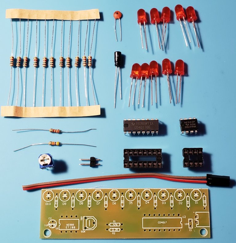
On to the fun. First up, lay out your components and confirm that you have everything. I've put together several of these packs that have been missing components. Usually it's just a simple capacitor or resistor. In this case we aren't short, but instead we have one extra 1k resistor! Score!
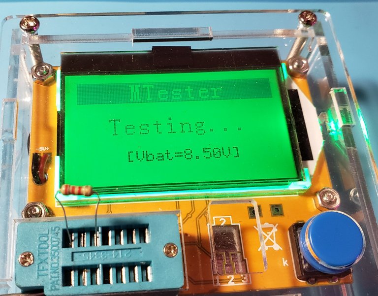
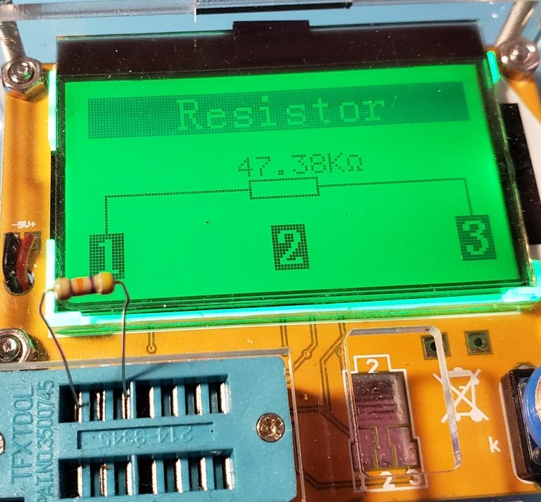
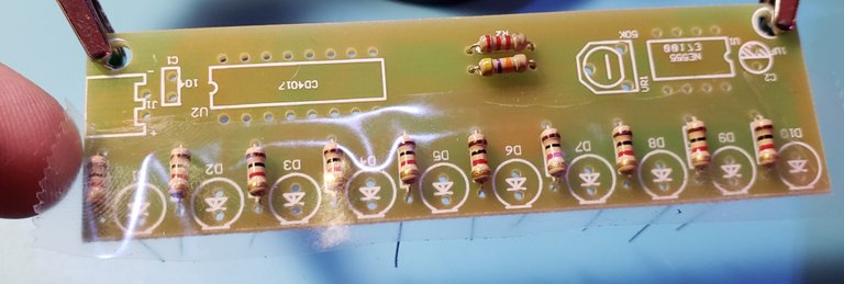
To begin we should test the resistors that were loose and solder them in place first. I have this handy component tester that tells me the value without having to pull out a multimeter and fiddle with the contacts. This device can tell diodes from capacitors and even tell you the pin output for a transistor. But we only need it for these resistors because the other components are either single pieces or multiples of ten. Still best practice to check your resistors just incase the factory sent you ten 10k resistors instead of 1k.
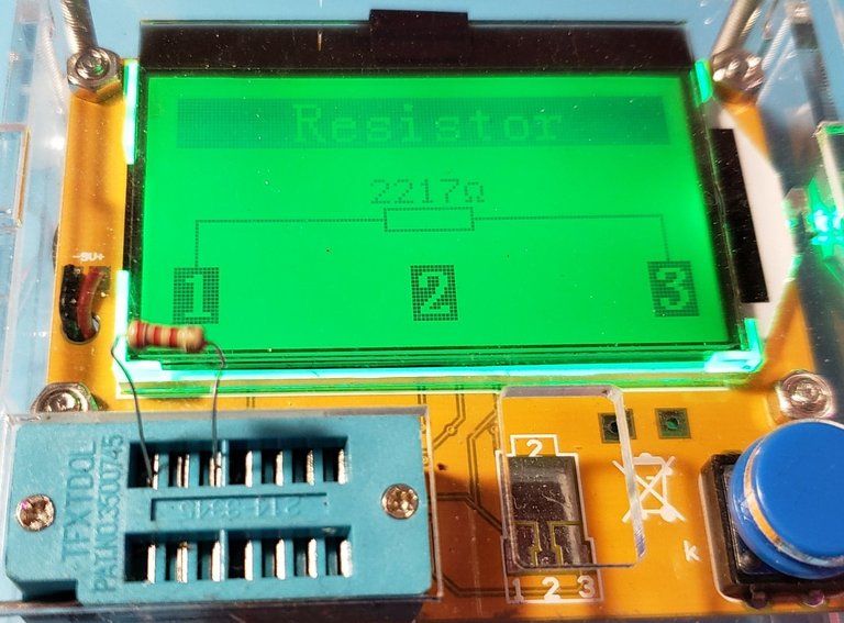
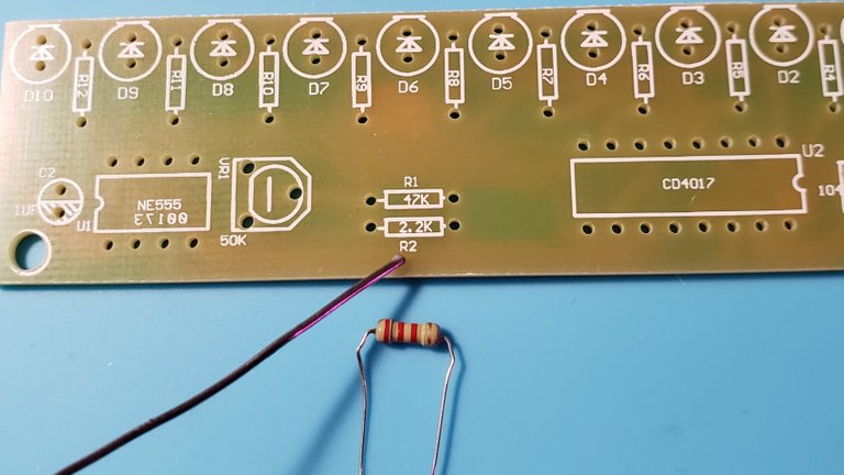
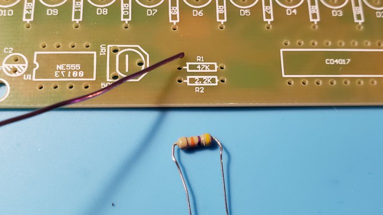
Make sure to put the 2.2k resistor in the proper spot along with the 47k resistor. Then bend the leads to keep the component in place, flip the board over and solder it together. I am not the best at soldering so if you want a tutorial on learning how to solder I suggest finding one on youtube.
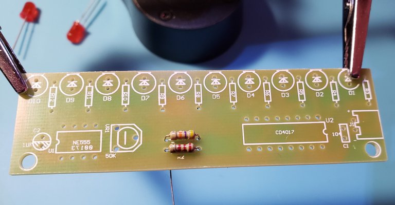
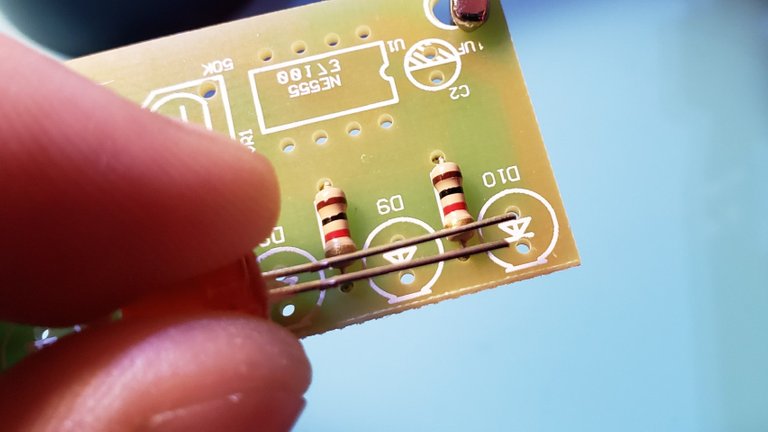
After you clip off the component leads it's time to add the 1k resistors to the board. To make soldering easier I put a piece of scotch tape atop the resistors to hold them in place. This is not the best solution, but I find it works in a pinch. People also use sticky tack or blue tack that you see in school. Again repeat the previous steps of solder, snip and flip it back over for more compnent to be added.
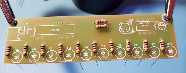
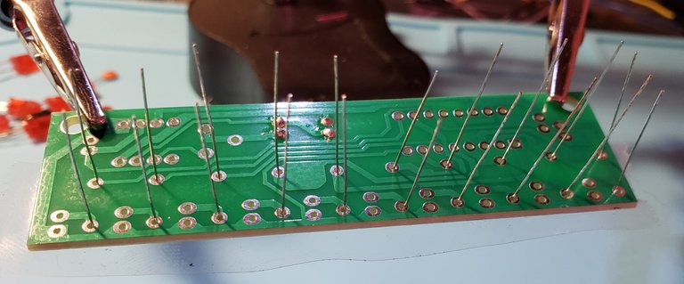
So many leads! That's why it's best to do components in batches rather than all at once. If we put the LED's on as well as the resistors it would be almost impossible to get our iron in there to solder the components to the board. With Resistors it doesn't matter which way you put them in, but most people prefer to put them in so all the colors line up. But you do you, rebel.
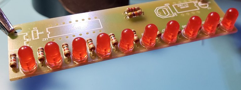
Just don't be a rebel with other components like Light Emitting Diodes. Their polarity of LED's matter because, as their name suggests, they function as diodes that emit light. Diodes only allow electricity to flow in one direction. The long leg is the Anode which gets positive voltage while the shorter leg is the cathode and it is connected to negative voltage. The little arrow shows the direction the electricity is flowing. I like to think of it as an A missing it's legs. A for Anode.
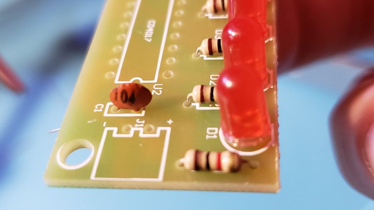
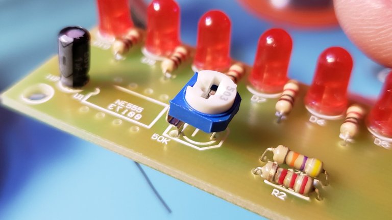
Electrolytic capacitors are like teeny crappy batteries. But they are only crappy as batteries. As capacitors they are awesome. They act to smooth out any voltage inconsistencies and allow components to remain at full power when the unit is under load. They are polarized as well which is usually noted with a white stripe down one side with a matching white half circle to represent its orientation. They also follow the rule of long lead being anode and short lead being cathode. At this point we will also add the potentiometer and the ceramic capacitor. The orientation of ceramic capacitors doesn't matter but you may wish to mount it in a way that allows you to see the numbers.
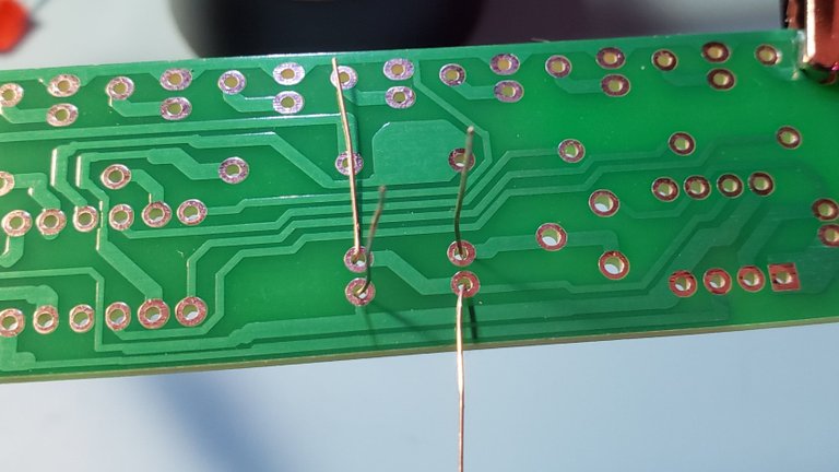
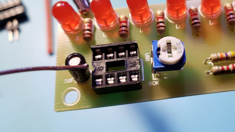
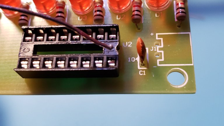
Next up is the integrated circuits. Or rather, their sockets. I forgot to take a picture of it before covering it up but there are little pips on the chips that denote the orientation the chip must face. Make sure to take note of it . I have pointed out the pips on the sockets. Match those to the board and when inserting the ic's to their sockets also make sure to align the pips.
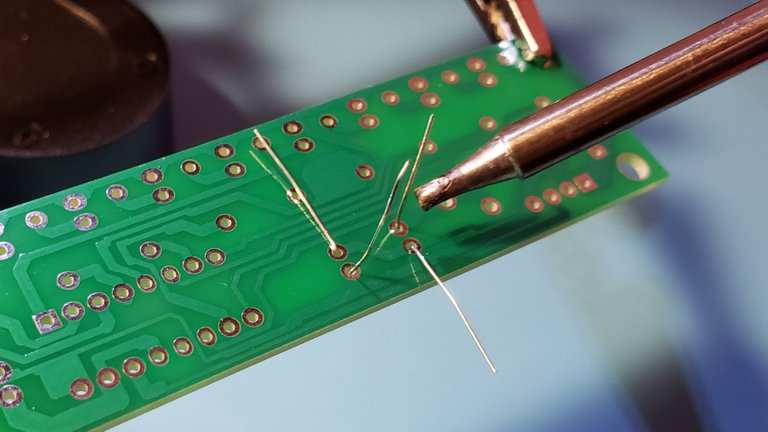
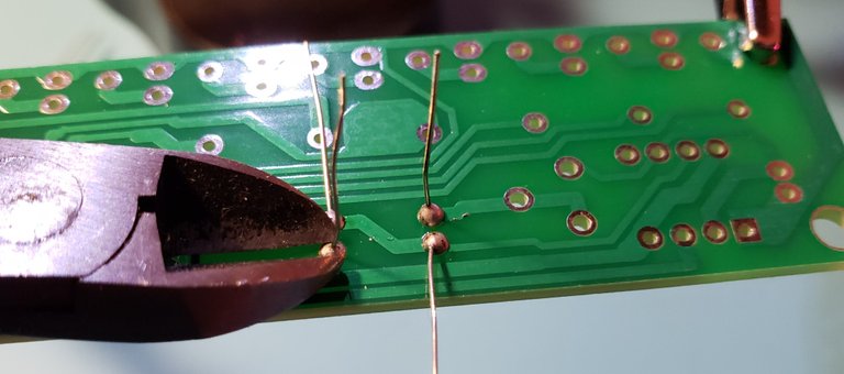
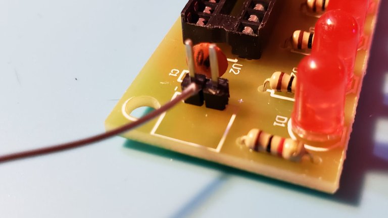
Finally, add the power connectors and solder them in place so you can provide power to the module.
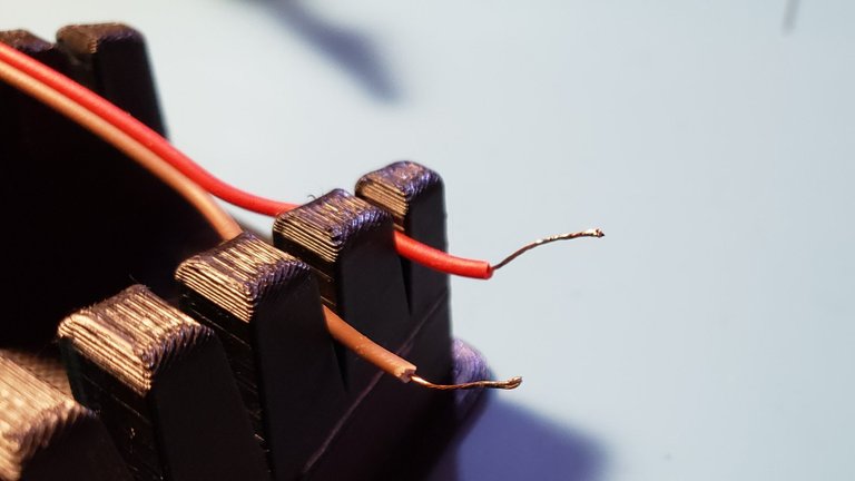
Strip some of the wirecasing back and tin the wires to prevent fraying when connecting to a power source.
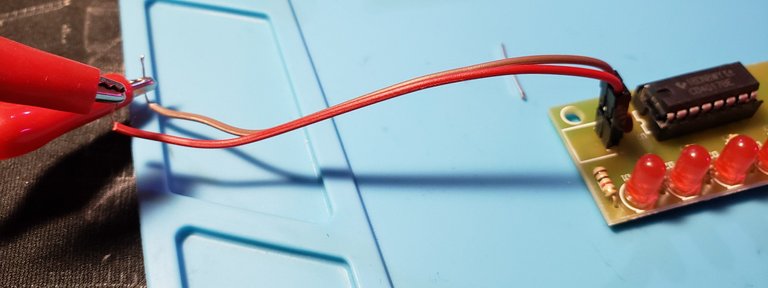
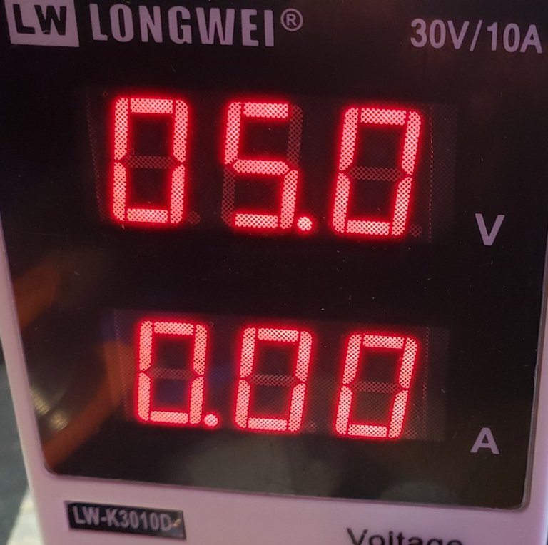
Supply the module with beetween 3 and 5 volts of DC power. This can be anything from the power supply that I'm using to a couple of AA batteries.
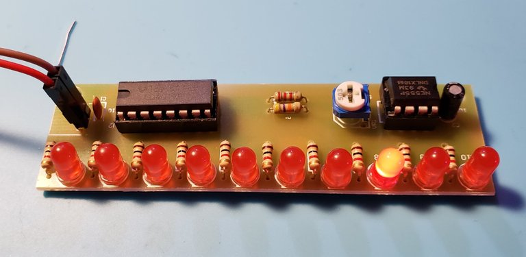
Hey, you're blinking!
Since pictures are a horrible way to show off a blinking string of lights I've provided this youtube video I whipped up to showcase the device.
All in all, this module should only take about 20-40 minutes to put together. I will say that this is more of a practice module meant for beginners to sharpen their soldering skills. The module itself isn't practical for much. But, like I mentioned earlier, you can totally use the compnents for this device to make other really cool projects. Google a Baby 8 Step Sequencer for example. I bought a few of these because they were cheap and had some relevant components to my needs. I plan on making my own Baby 8 soon.
Thank you for reading this post. I hope it helps you put together this kit if you run into some issues. The kit doesn't come with instructions, but it's not hard to figure out. The kit was purchased on banggood in a 3 pack for $4 CAD. I highly recommend all the diy electronic kits on Banggood for learning about electronics and building something cool.
Saw this on Twitter, my kinda project!
Electronics is fun!
This post was shared in the Curation Collective Discord community for curators, and upvoted and resteemed by the @c-squared community account after manual review.
@c-squared runs a community witness. Please consider using one of your witness votes on us here
Congratulations @greatnorthcrypto!
Your post was featured on our daily build newsletter! We've sent 100 liquid BUILD tokens to your wallet upon which you can sell, trade or buy on steem engine or SteemLeo. We've also shared your work on our Facebook and Twitter pages for more exposure.
Keep sharing your awesome DIY and How-to tutorials together with the recommended tags #diy, #build-it, #how-to, #doityourself, #build as well as posting from our website