I have searched the internet for an exact setup to install the Remote Control Display Panel for the Voltronic inverters as below but could not find any pictures how to extend the default cables supplied with the inverter. The problem is I needed to install it a long distance away and only a 6 Meter RJ45 to RJ45 Cable is supplied and a 6 Meter RJ12 to 2 Wires cable (Dry Contacts) Voltronic is the main chipset, picture below but it has been rebranded by several companies. The inside and firmware of the inverters remain the same.
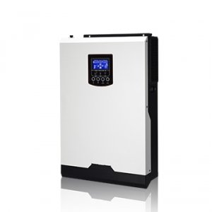
Inverter below - All the different brands Axpert, RCT, Infini Solar, Solar MD looks the same just different colors
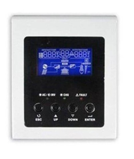
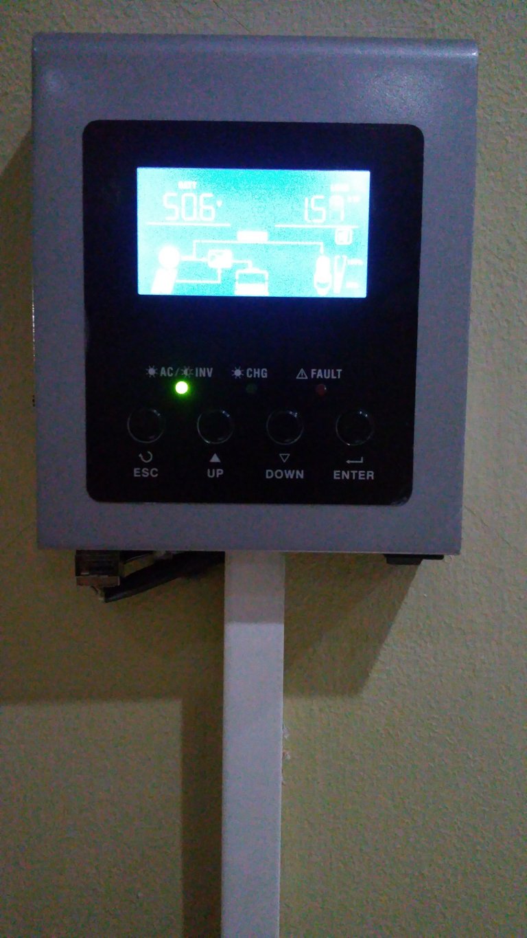
The Remote Control Display Panel to be installed is below
I needed the remote panel 60 meters away from where the inverters has been installed. CAT6 Outdoor UV Protected cabling has been used since my run was to the outside of the house and then inside again to a room 60 meters away. I needed to achieve this with one wire.
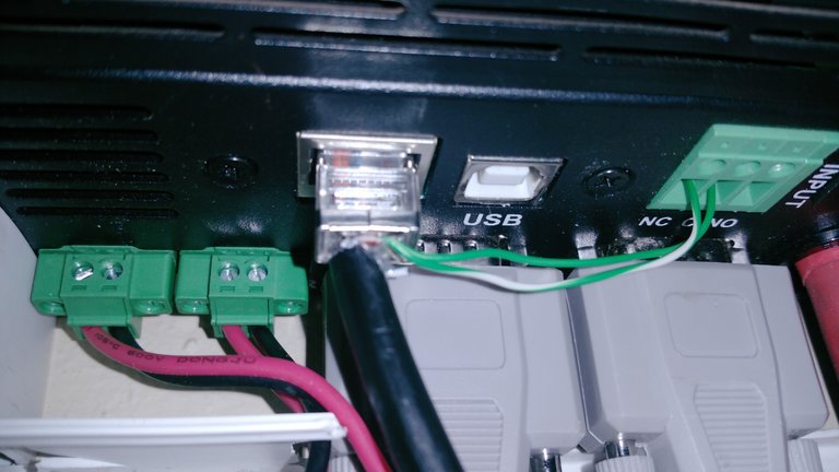
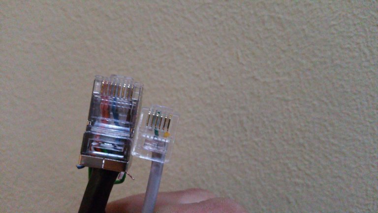
The included 6 Meter RJ45 to RJ45 cable was using only 4 wires on pins 1,2,4 & 8. I stripped the 60 meter Network Cable at both ends around 10cm due to the NC / C / NO contacts on the inverter being around 7cm away from the RJ45 port on the Inverter as in image below. I terminated (crimped) the one end nearest to the inverters of the 60 Meter CAT6 Cable with the default 568B Network Wiring color codes for pins 1,2,4 & 8 (White/Orange, Orange, Blue & Brown) and left the 4 additional wires to their 10cm length outside of the RJ45 Connector. I Then used the Green and White/Green wires to connect them as below to the NC / C of the inverter.
For the other end of the CAT6 Cable near the Remote Control Display Panel you can use a crimpon 6pin RJ12 connector but I did not have one nearby and just cut-off the supplied cable RJ12 Connector and attached the Green wire to Green on the CAT6 cable and the Yellow wire to the White/Green of the CAT6 Cable. It wasn't ideal to join the cable since it looked unprofessional but I used trunking to hide the joined cable away.
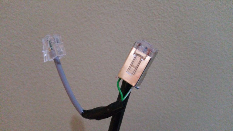
The RJ45 connector needs to be crimped exactly the same as the one near the inverters (Pins 1,2,4 & 8 used). Which is (White/Orange, Orange, Blue & Brown). The remaining 2 wires at each end can be cutoff or you can leave it as spare wires in case one of the other wires goes faulty.
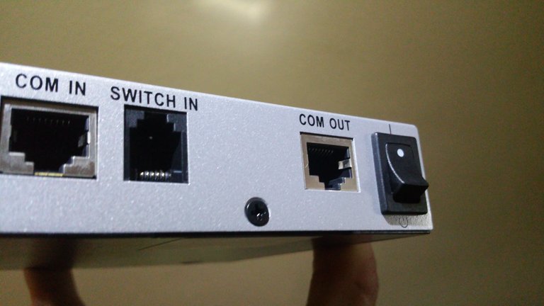
The RJ45 near the Remote Display Panel needs to be plugged into the "COM IN" port as below and the RJ12 6pin connector needs to be plugged into "Switch in" port.
After trunking installed the joined cable can be nicely hidden away if you did not have a crimpon RJ12 connector nearby and needed to join the cable. Final installation below.
✅ @thiartj, I gave you an upvote on your post! Please give me a follow and I will give you a follow in return and possible future votes!
Thank you in advance!
Hey hey, howzit @thiartj. Welcome to the community!
My cousin, @deanoza let me know you've joined recently. You should come and join us on the teamsouthaftica Discord group. I'd be happy to offer some advice and assistance to get you going on your journey.
It can be difficult to get going so best is to get connected within communities. I'll be sure to keep a lookout for those that will suit your type of blogging :)
Here is the tsa Discord link: https://discord.gg/uqfyGb
Cheers!