Hallo Elektronikfreunde.
Nun fehlt noch das DSP5015 Modul
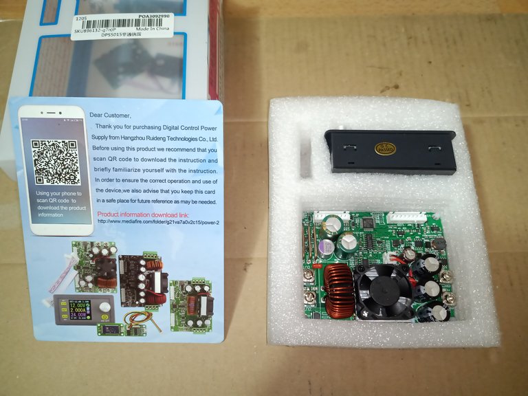
Bild 01 zeigt das Modul in der Originalverpackung.
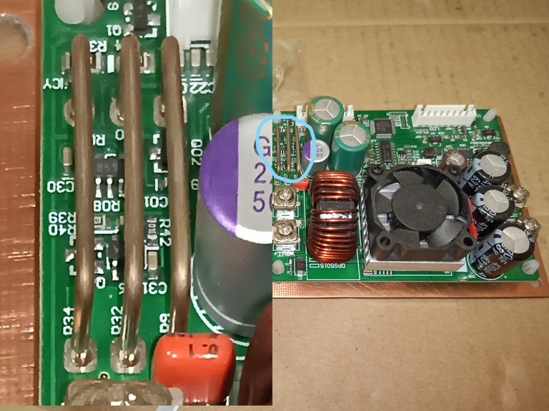
Bild 02
Gut zu erkennen die Shunt-Widerstände (3 Drahtbrücken links im Bild).
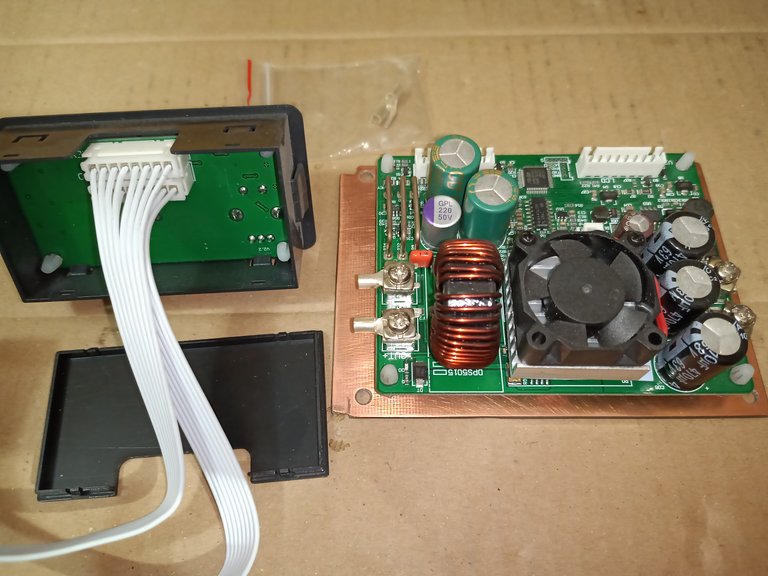
Bild 03
Leider passen die Befestigungen des Modules nicht in das Raster des Gehäuses. Deshalb musste ich eine Adapterplatine zur Aufnahme das Leiterplattenmodules anfertigen
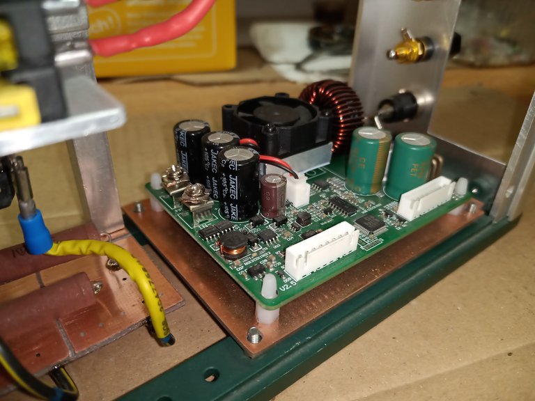
Bild 04 zeigt, wie das Ganze im Gehäuse seinen Platz findet.

Bild 05
Zwischen den Anschlüssen befinden sich SMD Sicherungen. Im Bild 05 zu sehen die Out-Anschlüsse und dazwischen, die Sicherung mit F2 bezeichnet. Der Wert ist 20A.
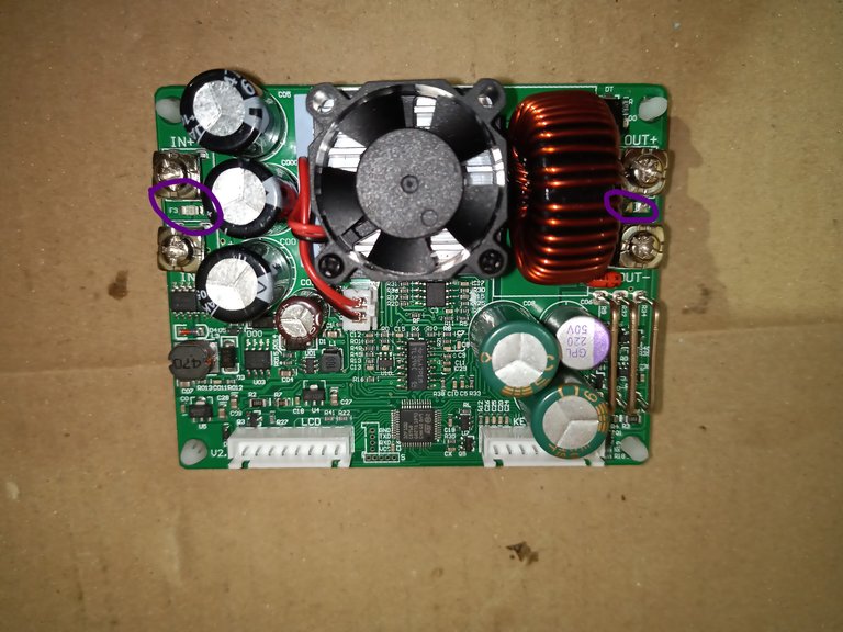
Bild 06
Auf der In-Seite befindet sich F3 mit ebenfalls 20A. Diese sind also bei einem Gerätedefekt ebenfalls zu kontrollieren und gegebenenfalls auszutauschen.

Bild 07: Ein erster Funktionstest mit 2 Lampen als Last
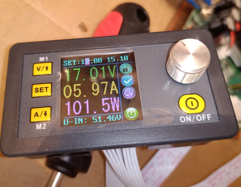
Bild 08 der Belastungstest mit 100Watt (ca.6Ampere)
Nun kann das Modul eingebaut werden, um dann die Endmontage und den finalen Belastungstest durchzuführen.
Fortsetzung folgt …….
google translator
Hello electronics enthusiasts.
Now the DSP5015 module is still missing
Fig. 01 shows the module in the original packaging.
Picture 02
The shunt resistors are clearly visible (3 wire jumpers on the left in the picture).
Image 03
Unfortunately, the attachments of the module do not fit into the grid of the housing. So I had to make an adapter board to accommodate the PCB module
Fig. 04 shows how everything fits into the housing.
Picture 05
There are SMD fuses between the connections. In picture 05 you can see the out connections and in between, the fuse labeled F2. The value is 20A.
Image 06
On the In side there is F3 with 20A as well. In the event of a device defect, these should also be checked and replaced if necessary.
Fig. 07: A first function test with 2 lamps as a load
Fig. 08 the load test with 100 watts (approx. 6 amps)
Now the module can be installed in order to carry out the final assembly and the final load test.
Sequel follows …….