
In this tutorial I will be demonstrating how you could go about ramping an axis using a Rockwell Micrologix processor.
The reason I initially wrote this logic was due to an issue on a Ram-70e machine I was programming. The machine consisted of a clamp and a ram. The ram was to hold a position to which a tube was butted up against at the beginning of each cycle. When the cycle would be initiated and the clamp began to close, the ram would 'lunge' by at least .100". This is unacceptable in the terms of precision.
Diagnosing the issue, it was decided, due to the fact both the clamp cylinder and the ram cylinder had a common supply, we must be seeing the loss of fluid holding the pilot spool of the valve centered. This loss of, or rather lack of fluid, even in the short time span it is seen, creates a differential in pressure at the spool. Thus allowing the spool to shift ever so slightly, for a fraction of time. This allows the main valve of the ram to be shifted which then allows the fluid to move and thus the motion to occur.
The kicker is that the ram is on a servo. So at the precise moment it begins to move, as the spool shifts, the motion controller tries to correct the axis back into position. As it would happen, this seems to be when that differential in pressure dissipates thus returning the pilot back to normal. However, now the motion controller has begun to ramp up to correct for the out of position condition created. Now we are beginning to saturate, and possibly oscillate the axis.
The fix we came up with was a down and dirty ramp up for the clamp. This should smooth out the draw of fluid into the clamp cylinder at a slower rate. This will allow the pump to 'keep up' a bit better, and the differential of pressure we were seeing at the pilot spool of the ram should be minimized.
The problem arises due to the fact that the operator sets a speed for the clamp. When the clamp is issued a move command it starts out at whatever speed the operator has entered, no matter if it's 1 (pu/s) or 20 (pu/s). The faster the speed is set, the more the initial consumption of fluid will be. We need to slow the rate.....
We can do this with 2 lines of logic. Here is a screen shot of the two rungs. I wrote these 2 rungs with generic descriptions for the data files.
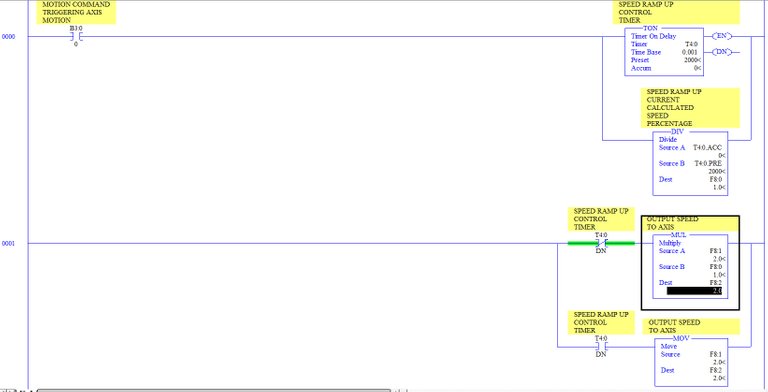
You can see here, once the motion command is issued a timer begins. This timer has a preset for the time duration of the ramp. In this case 2000 is equivalent to 2 seconds. So this ramp will happen over a 2 second time frame. At the instance the axis sees the move command, the current speed would be (0 / 2000) * Set Speed.
As the axis moves, the timer would be accumulating. Say the accumulation had made it to .130 seconds. The speed would be (130 / 2000) * Set Speed or 0.065 * Set Speed. Let's say the move was at 1.4 seconds in, at that time the speed would be (1400 / 2000) * Set Speed or 0.7 * Set Speed.
In the second rung you can see after the 2 seconds have expired, the multiplication of speed is not used. You could leave the calculation 'in-play' if you wish, as once the timer is done, the value would equal Set Speed * 1.
Until next time:
Relay
Congratulations @jamescash! You have completed the following achievement on Steemit and have been rewarded with new badge(s) :
Click on the badge to view your Board of Honor.
If you no longer want to receive notifications, reply to this comment with the word
STOPTo support your work, I also upvoted your post!
Do not miss the last post from @steemitboard:
SteemitBoard World Cup Contest - The results, the winners and the prizes