In this blog we are going to cover how to interface the SWITCH, to microcontroller and control the LED. If you don’t know how to use the MPLABX IDE v4.40 so please visit to my previous blog I have shown you in detail step-by-step procedure.
So let’s start……
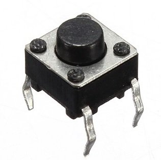
In this blog we going to use switch (push button). Push button is simply a mechanical switch which can be make or break connection. Whenever we press the push button it establish the connection and current start flowing through it. As we release the button connection get breaks an flow of current get stop.
CIRCUIT DIAGRAM:-
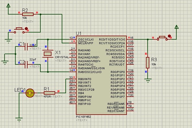
Here switch is connect to pin RC0 of PORT C, which is configured as input pin. An LED is connect to PORTB (RB0).When we press the switch LED Glows & when we release the switch LED turn OFF.
**PROGRAM:-
#define _XTAL_FREQ 12000000 //20MHz crystal is used
#include <xc.h>
// PIC18F452 Configuration Bit Settings
// 'C' source line config statements
// CONFIG1H
#pragma config OSC = HS // Oscillator Selection bits (HS oscillator)
#pragma config OSCS = OFF // Oscillator System Clock Switch Enable bit (Oscillator system clock switch option is disabled (main oscillator is source))
// CONFIG2L
#pragma config PWRT = OFF // Power-up Timer Enable bit (PWRT disabled)
#pragma config BOR = ON // Brown-out Reset Enable bit (Brown-out Reset enabled)
#pragma config BORV = 45 // Brown-out Reset Voltage bits (VBOR set to 4.5V)
// CONFIG2H
#pragma config WDT = ON // Watchdog Timer Enable bit (WDT enabled)
#pragma config WDTPS = 128 // Watchdog Timer Postscale Select bits (1:128)
// CONFIG3H
#pragma config CCP2MUX = ON // CCP2 Mux bit (CCP2 input/output is multiplexed with RC1)
// CONFIG4L
#pragma config STVR = ON // Stack Full/Underflow Reset Enable bit (Stack Full/Underflow will cause RESET)
#pragma config LVP = OFF // Low Voltage ICSP Enable bit (Low Voltage ICSP disabled)
// CONFIG5L
#pragma config CP0 = OFF // Code Protection bit (Block 0 (000200-001FFFh) not code protected)
#pragma config CP1 = OFF // Code Protection bit (Block 1 (002000-003FFFh) not code protected)
#pragma config CP2 = OFF // Code Protection bit (Block 2 (004000-005FFFh) not code protected)
#pragma config CP3 = OFF // Code Protection bit (Block 3 (006000-007FFFh) not code protected)
// CONFIG5H
#pragma config CPB = OFF // Boot Block Code Protection bit (Boot Block (000000-0001FFh) not code protected)
#pragma config CPD = OFF // Data EEPROM Code Protection bit (Data EEPROM not code protected)
// CONFIG6L
#pragma config WRT0 = OFF // Write Protection bit (Block 0 (000200-001FFFh) not write protected)
#pragma config WRT1 = OFF // Write Protection bit (Block 1 (002000-003FFFh) not write protected)
#pragma config WRT2 = OFF // Write Protection bit (Block 2 (004000-005FFFh) not write protected)
#pragma config WRT3 = OFF // Write Protection bit (Block 3 (006000-007FFFh) not write protected)
// CONFIG6H
#pragma config WRTC = OFF // Configuration Register Write Protection bit (Configuration registers (300000-3000FFh) not write protected)
#pragma config WRTB = OFF // Boot Block Write Protection bit (Boot Block (000000-0001FFh) not write protected)
#pragma config WRTD = OFF // Data EEPROM Write Protection bit (Data EEPROM not write protected)
// CONFIG7L
#pragma config EBTR0 = OFF // Table Read Protection bit (Block 0 (000200-001FFFh) not protected from Table Reads executed in other blocks)
#pragma config EBTR1 = OFF // Table Read Protection bit (Block 1 (002000-003FFFh) not protected from Table Reads executed in other blocks)
#pragma config EBTR2 = OFF // Table Read Protection bit (Block 2 (004000-005FFFh) not protected from Table Reads executed in other blocks)
#pragma config EBTR3 = OFF // Table Read Protection bit (Block 3 (006000-007FFFh) not protected from Table Reads executed in other blocks)
// CONFIG7H
#pragma config EBTRB = OFF // Boot Block Table Read Protection bit (Boot Block (000000-0001FFh) not protected from Table Reads executed in other blocks)
// #pragma config statements should precede project file includes.
// Use project enums instead of #define for ON and OFF.
#define SW RC0 // here we have given name SW (Switch) to RC0 pin
#define LED RB0 // here we have given name LED to RB0 pin
int main()
{
TRISB0 = 0; //RB0 as Output PIN
TRISC0 = 1; //RC0 as Input pin we are going to connect switch here.
while(1)
{
if(SW == 1)
{
LED = 1; // LED ON
__delay_ms(1000); // 1 Second Delay
}
else
{
LED = 0; // LED OFF
__delay_ms(1000); // 1 Second Delay
}
}
return 0;
} **
In code we had used # define SW RC0 and # define LED RB0 above the int main() function, because these macro definitions allow constant values to be declared for use throughout your code. We had used 10millesec delay to avoid the debouncing effect of switch.
Hi! I am a robot. I just upvoted you! I found similar content that readers might be interested in:
https://stackoverflow.com/questions/33025173/pic18f2520-reset
Congratulations @niyo64! You have completed some achievement on Steemit and have been rewarded with new badge(s) :
Click on any badge to view your own Board of Honor on SteemitBoard.
For more information about SteemitBoard, click here
If you no longer want to receive notifications, reply to this comment with the word
STOP