A huge greeting to the entire community !! I hope they are well👍. A few days ago I uploaded a post announcing a project in which I have been working, it is an outlet with protection against fluctuations in the electrical network. In recent days, I have spent more time than normal to advance the project, analyzing the aspects that could be improved. It turns out that indeed I have made an improvement to both the schematic diagram and the printed circuit board, reducing its size somewhat, as well as adding a second voltage input.
Este era el diseño anterior de la PCB ⬇️⬇️
This was the previous PCB layout ⬇️⬇️
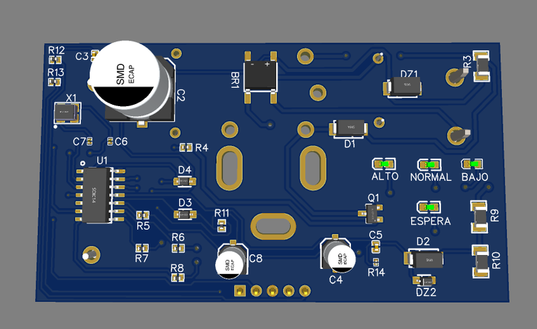
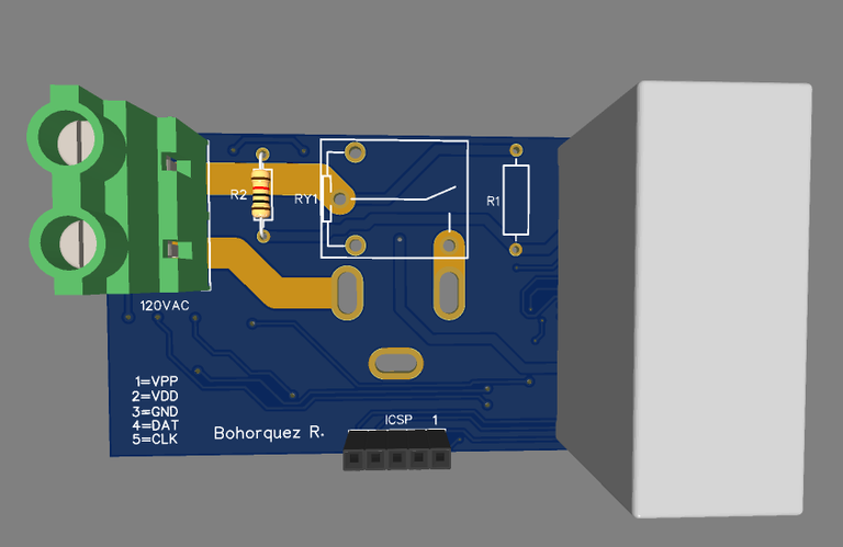
Me tomó algo de tiempo rediseñar la placa🔎, pero al final la terminé y pienso que se ve muy bien, entre las cosas que le agregue como mencioné anteriormente fue una segunda entrada de tensión, es decir otro conector de color verde como el que se ve en la imagen, quiero descatar que tales conectores fungen como entrada y a su vez como salida de tensión alterna, como salida debido a que en ocasiones se debe derivar dicha tensión entrante hacia otro punto. También eliminé el condensador de 2uF 250V, es ese que se ve como un rectágulo blanco enorme, fue reemplazado por dos condensadores de 1uF 250V, ésto por cuestiones de reducción de carga de trabajo.
It took me some time to redesign the board🔎, but in the end I finished it and I think it looks very good, among the things that I added as I mentioned earlier was a second voltage input, that is, another green connector like the one you see In the image, I want to rule out that such connectors function as an input and as an output of alternating voltage, as an output because sometimes said incoming voltage must be diverted to another point. I also eliminated the 2uF 250V capacitor, it is the one that looks like a huge white rectangle, it was replaced by two 1uF 250V capacitors, this for workload reduction reasons.
Este es el nuevo diseño⬇️⬇️
This is the new design ⬇️⬇️
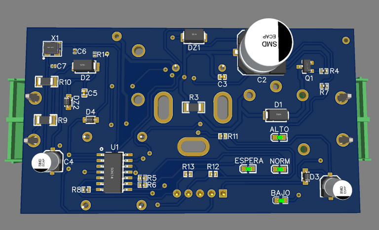
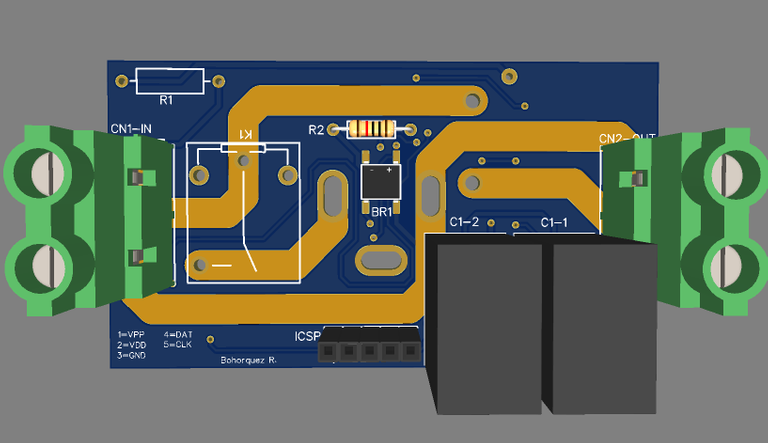
Se preguntarán que son esas líneas doradas. Son pistas conductoras de eléctricidad, pero éstas debido a su gran tamaño se encargarán de manejar corrientes superiores a los 5 Amperios⚡️, intensidad que no es capaz de ser soportada por una pista común. Estos trazos posteriormente serán reforzados con estaño, para asegurar la conducción y el paso de la corriente sin problema de recalentamiento🔥 en la misma.
You may wonder what those golden lines are. They are electrically conductive tracks, but due to their large size, they will handle currents greater than 5 Amps⚡️, an intensity that is not capable of being supported by a common track. These lines will later be reinforced with tin, to ensure the conduction and the passage of the current without overheating🔥 problem in it.
Próximamente iré realizando de ser necesario alguna modificación y también trabajaré en el diseño para un tomacorrientes con protección doble entrada, así mismo les iré comentando los avances y como se irá desarrollando dicho proyecto, les agradezco su tiempo y esto ha sido todo por hoy. Nuevamente los invito a que sigan trabajando💪 en sus proyectos y en sus sueños, y no se desanimen cuando las cosas se empiezan a complicar, es normal, pero debemos seguir adelante, un gran abrazo a todos!!
Soon I will be making any modifications if necessary and I will also work on the design for an electrical outlet with double entry protection, I will also comment on the progress and how this project will be developed, I thank you for your time and this has been all for today. Again I invite you to continue working 💪on your projects and dreams, and do not be discouraged when things start to get complicated, it is normal, but we must move on, a big hug to all!
Congratulations @bohorquez19! You have completed the following achievement on the Hive blockchain and have been rewarded with new badge(s) :
Your next target is to reach 200 upvotes.
Your next target is to reach 50 replies.
You can view your badges on your board and compare yourself to others in the Ranking
If you no longer want to receive notifications, reply to this comment with the word
STOP