The information generated in the sensors is sent to the microcontroller of the PLC, through elements that serve to isolate the environmental stage where the sensors are, from the control stage that is understood by the central processing unit of the PLC and that is inside the microcontroller. The isolation elements are called input modules, which are identified and referenced to the temporary memory blocks where the sensor data are stored.

As for the data that manipulate the actuators (also called output data), these are housed in temporary memory locations that are exprophesically reserved for such information. When in the process of execution of a user program a response is generated and this in turn must modify the operation of an actuator, the data is stored in the corresponding temporary memory location, taking into account that this data represents an information bit and that each memory location has space for 8 bits.
Once the output data have been stored in the corresponding memory locations, in a later cycle the microcontroller can communicate them to the outside of the PLC, since each bit that makes up an output data byte has a reflection as to the physical connections that the PLC has to the power elements or actuators, or in other words, as in the input data terminals, each of the terminals that contain the output information also has a power element connected to its corresponding terminal.As the microcontroller of the central processing unit of the PLC executes the instructions of the user program, the temporary memory block assigned to the data output is being continuously updated since the output conditions often affect the result that the execution of subsequent instructions of the user program can bring about.
According to the way in which the output data are handled, it can be observed that this information fulfills a double activity, being the primordial one to channel the results derived from the execution of the instructions on the part of the microcontroller, towards the corresponding blocks of memory, and also to pass the output data to the terminals where the actuators are connected. Another function is to feed back the output information to the microcontroller of the central processing unit of the PLC, when any instruction of the user program requires it. As far as input data are concerned, they do not have the dual function of output data, since their mission is solely to acquire environmental information through the input terminals and make it reach the microcontroller of the central processing unit.
The output data as well as the input data are guided to the respective actuators through electronic elements that have the function of isolating and protecting the microcontroller of the central processing unit with the power stage, these elements are called output modules.
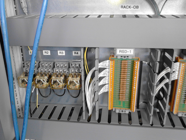
Both the input and output modules have a direct connection to the terminals of the input and output ports of the PLC microcontroller, this connection is made through a base that inside has a link bus associated with a series of connectors that are the physical means where the modules are inserted (either input or output). The total number of input or output modules that can be added to the PLC depends on the number of addresses that the microcontroller of the central processing unit is able to observe.
According to what is written in the previous paragraph, each data (either input or output) that is represented by a bit and that in turn is grouped in blocks of 8 bits (word or byte), must be registered and identified so that the microcontroller "knows" if it is being occupied by a sensor or an actuator, since certain bit of specific byte and therefore of certain temporary memory location has its reflection towards the physical terminals of the modules. This last one means that in the connectors of the base both the input modules and the output modules can be connected in an indistinct way, reason why the flow of information can be towards the microcontroller of the central processing unit or, in opposite direction.
With respect to the memory where the user program is housed, it is of the EEPROM type, in which the information is not erased unless the user does so.

This concludes another installment that I leave for you with much affection hoping that I can be of use to you and sincerely thanking you for the time you have taken to read my article.
All images used in this article are my own, photographs taken during my professional work. I allow the use of these images as long as they are mentioned to me in the article and the source is cited.
Steemit is expanding to other blog ecosystems, will soon be official with Smart Media Tokens and is already possible for WordPress thanks to the steempress plugin, a revolutionary initiative. If you wish to support the project I invite you to vote for @steempress as a witness by clicking here

Posted from my blog with SteemPress : https://automation80.000webhostapp.com/2018/09/signals-in-a-plc