In this article I will be detailing one of the coolest experiments I have done thus far with my vacuum system. Through some very simple observations of plasma, I was able to create a mini thruster which directs plasma and electrons out of its nozzle just like a rocket engine! Being an Aerospace engineering student, it was only a matter of time before I built my own plasma thruster! As usual, I will explain the science behind its operation as best as I can and will provide some further reading below!
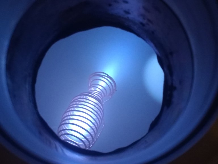
Figure 1. Plasma blasts out of the nozzle on the engine
How a rocket engine works
Before I dive into how this electron thruster operates, it would be beneficial to go over how a conventional chemical rocket works. For this purpose, I am going to borrow a diagram from NASA since they do a bit of dabbling in rocket science!
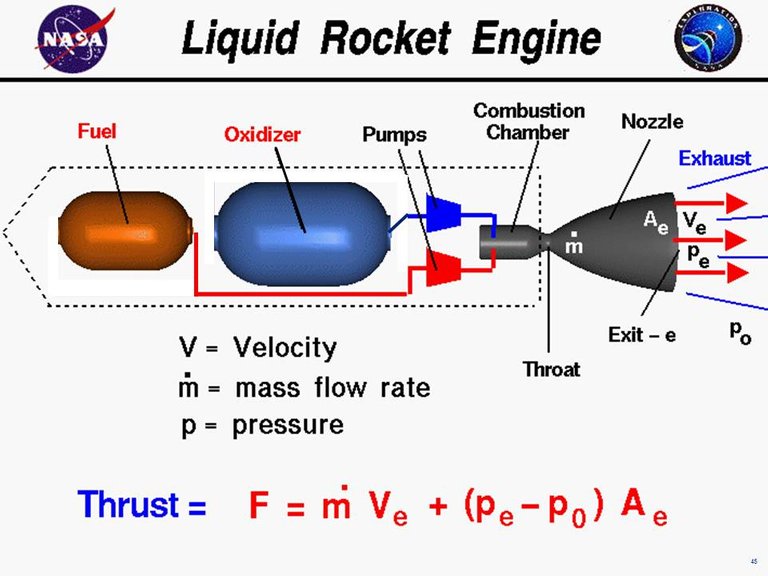
Figure 2. Basic diagram of a liquid fueled rocket engine. (Image from NASA)
An engine works by extracting the chemical energy within a fuel and oxidizer mix and converting that into thrust. The fuel and oxidizer are mixed within the combustion chamber where they are ignited and burn releasing tremendous amounts of energy. This thermal energy is then converted into kinetic energy through the use of a de Laval nozzle. The operation of a rocket nozzle is very complicated and if you would like more information please use the Further Reading section below. This kinetic energy is then transferred to the vehicle which causes it to accelerate. This is how basic rockets work!
Plasma Thruster 1.0
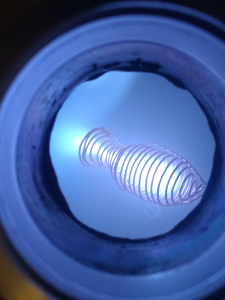
Figure 3. Dense bright plasma within the main chamber is clearly visible.
The engine that I built operates substantially differently but maintains a few core similarities. For starters, there is still a "fuel" and there is a source of heat. The engine also generates thrust by shooting mass out of a nozzle! Of course, the same laws of physics and thermodynamics apply. Now before you get excited about blasting off into space with your brand new plasma rocket-pack, I have to dash your dreams with science. Unfortunately, the thrust generated by this method, and other plasma thrusters, is incredibly small. The record, according to Wikipedia, is currently around 5 Newtons of thrust in a lab environment! The reason they are still used is they are extremely efficient which can be read in more detail in the Further Reading section. I am unable to measure the thrust of my engine with the equipment I have, but it is so small it probably less than .001 Newton.
The propellant that I used for this thruster is simply residual gas left inside of the vacuum chamber. This residual gas drifts about the interior of the vacuum chamber and eventually some of it ends up drifting into the engine body. Since the gas molecules are neutral, they are not attracted or repulsed by the strong electric field surrounding the chamber body(further explained below) allowing them to drift into the cloud of swirling electrons in the center of the engine. These gas molecules are then struck by electrons, turning them into ions which creates the bright plasma. Some of these newly formed ions get carried with the electrons out of the engine body while some collide with the wire and become neutral again. In this sense, the fuel is reusable as long as it drifts back into the engine at some later point in time. The only true input into this system is energy in the form of electric potential and current. Electrons are emitted from the negatively charged engine body and some become trapped within, forming the electron cloud. An additional bonus is that any positive ions that form outside of the engine will be attracted to the negative potential engine, and thus increase the concentration of free gas to be used as fuel near the engine!
Now you may look at my plasma thruster and think "Well there are no walls! How can it hold back the plasma?!". The answer is through a virtual wall, or electric field. The spiral shape that encases the plasma is actually copper wire which is connected to a negative high voltage terminal. This high voltage generates a large negative electric field around the wire coil which repulses other negative charges, such as electrons. This allows you to confine negative electric charges! To help illustrate this point, I am going to use a diagram from one of my previous articles.
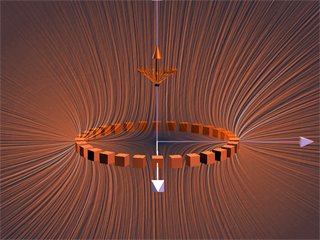
Figure 4. The orange lines represent electric field lines and the more there are in a given area, the stronger the field. Note the dark spot within the ring structure
Extrapolating from the Figure 4, we can gather that there will be a low electric field in the center of a coil that is electrically charged. What this does is creates a strong electric field around an area of low electric field which is exactly what you want for containing a plasma! Once charged particles are created near the electric field, they are repulsed into the lower field region in the center of the structure. This occurs until enough particles accumulate that the charge in the center is comparable to the charge containing the particles. By this point, a dense ball of plasma has formed due to the large number of electrons bouncing around. Once they reach this equilibrium point, they look for a weak point in the field to escape. Think of squeezing a half-full water bottle with a tiny hole in the lid. As you squeeze, water fills up the air pockets until it entirely fills the bottle. At this point, the pressure is equalized and if you squeeze anymore, water will shoot out the top. This is very similar to how the Plasma Thruster 1.0 works. Figure 5. displays this plasma plume leaking out of an unintended point due to a bent wire and thus a weak point in the electric field.
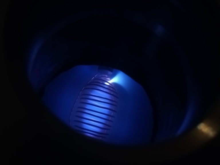
Figure 5. Plasma leaking out the side of the thruster body
I showed many of these images in my previous article and an idea came to mind when I was reviewing them. If you artificially make the weak point, you can choose where you shoot the plasma and direct it! This lead to the current design of the plasma thruster. Adding a nozzle keeps the plume directed out and away from main body. There isn't too much to the design other than a little bit of wire wrapping, the physics takes care of itself! Hopefully this was a sufficient explanation of how the Plasma Thruster 1.0 works!
More Images!
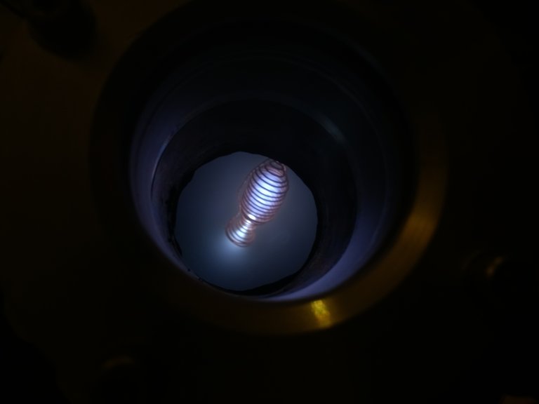
Figure 6. Electrons are accelerated through the nozzle which creates a denser and hotter plasma in the throat(white area)
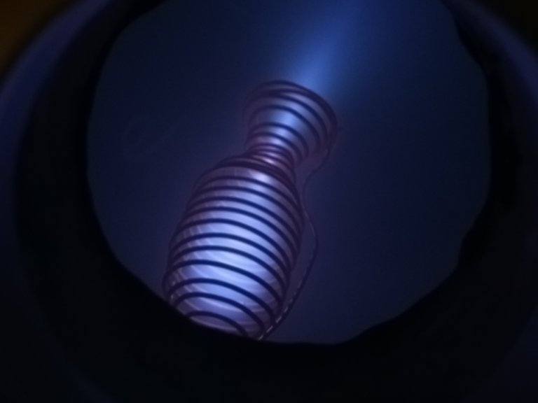
Figure 7. A lower vacuum chamber pressure pushed the flow towards molecular conditions
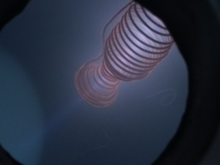
Figure 8. Beam of electrons blasting out from the nozzle due to molecular flow conditions. Note the orange glow coming from the surface of the copper.
Note regarding the orange glow
I am not sure what the cause of this is yet and will continue to investigate it!
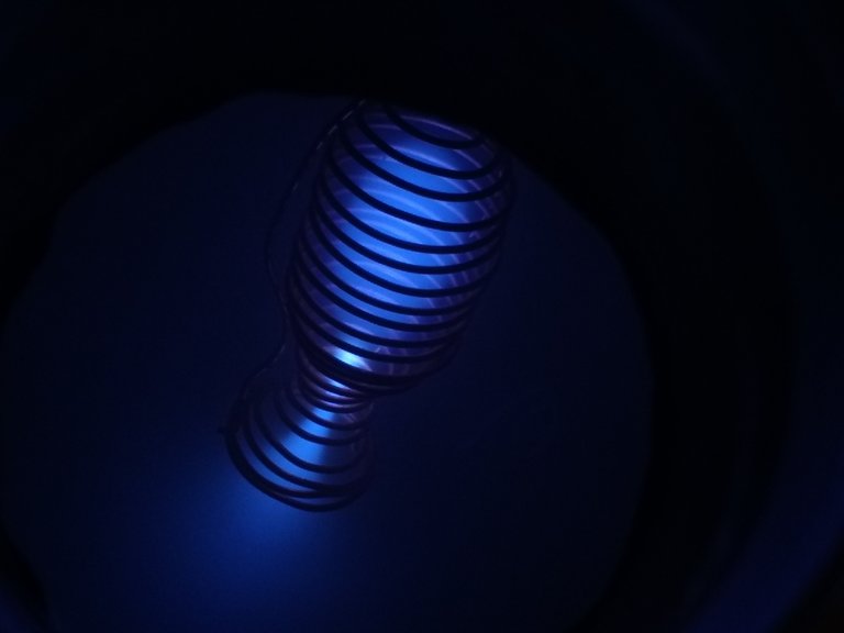
Figure 9. Lower voltage applied than in the other images. The nozzle throat still is a white hot plasma.

Figure 10. GIF showing the transition from a leaky plasma to normal operation to molecular beam. GIF is playing in real time.
If you have any questions or suggestions, let me know in the comment section!
Further Reading
Sources
Charged Ring: https://physics.stackexchange.com/q/337905
Liquid Rocket Engine Diagram (NASA)
This is awesome!!! You have basically built a demo-fusor, which can fuse deuterium atoms if you pump deuterium gas in there and set up the vacuum/voltage correctly.
You should consider using the #steemstem tag for high-quality projects like this.
Brilliant work!
I will use the #steemstem tag in the future! Thanks for the advice!
I plan on making a fusor in the future. I have a decent number of the parts, I just need a few more flanges and some deuterium and it'll be golden!
oh thanks I totally meant to pass on that tip RE using #steemstem as well but completely forgot by the time I got to the bottom of this amazing post :)
What sort of propellant are you using for this? Also describing this as a plasma engine isn't the best, especially if you put down a liquid rocket engine design as a diagram and then put ion thrusters for further reading :P. Are we talking here like a typical hydrazine engine or what.
Thank you for the input! I was going to write a paragraph about the fuel but then it just escaped me.
The purpose for the regular rocket diagram was to describe the basic process of a rocket operation, essentially conservation of mass and momentum, but in more simple terms. The plasma thruster operates by kicking out low mass high velocity particles (similar to an ion engine) from the nozzle. I must have done a poor job getting the comparison in there so I apologize for that!
The big point I missed was the fuel. So the reason that the walls are open and in a coil shape is that it uses residual gases as the thrusting medium as well as electrons. Electrons are stuck in the low potential region within the plasma and then once they build up enough pressure, which occurs extremely quickly, they then jet out the nozzle at very high velocities and take some gas molecules with them. I could not get a good picture of it, but there is a dull green glowing zone where the nozzle is pointing on the inside of the chamber wall. At lower pressures(where it comes out like a beam), you essentially are only firing electrons out of the rocket and they behave much more like electron gun than a thruster. So the propellant is a mix of electrons, water molecules, hydrogen, nitrogen, oxygen, and a few trace gases. Its just leftover air.
Hopefully this clarifies some things!
Never to late to edit that in ;)
I have edited information in. I was not aware that was a feature, thanks!!!!
No problem :D
Cool Bro!! Everyone are good at theoretical knowledge but you are one step ahead than others, you have put the practical application and above all you have let us witness it.. that is so nice of you :)
Instead of an electric field containment system, have you looked into magnetic containment? Being 90 degrees to the electrical it may work and create further power efficiencies perhaps?
Yes I have! I built this one first because it was very simple and I don't think anyone had tried this particular setup before. I plan on building a hall effect thruster at some point soon which uses magnetic containment!
Excellent @hellfire-labs. I might have missed something in this description, what sort of plasma/gas is being used to impart momentum. Are you saying you are imparting momentum just via electrons? The reason I ask is because I know the ones in use, use a gas like Xenon which is large atom.
I intended to write than in my article then completely spaced about that part so I apologize for that.
I use the residual gas to impart momentum on the nozzle. So the gas remaining in the vacuum chamber is the fuel. The electrons strike the stray gas molecules when they drift into the coil as well as on their way out the nozzle. The large flux of electrons exiting the nozzle also carries some gas molecules with it. This is why the engine has a lot of gaps in its structure, to allow the fuel to drift in! Unfortunately, I do not have to tools to do the thorough analysis that is required to determine the actual thrust levels and what is the main cause of that thrust, so I can't get a definite answer as to what the primary mode of thrust generation is. My speculation is that it is the residual ions due to them having a much higher mass.
Very cool! The GIF at the end showing the plasma transition in particular is very interesting to watch
Wow this is so cool! Did you get the bigger viewport? It seems like the pictures are clearer / easier to see what is going on this time. The gif in particular is awesome. Now that this thing is fired up, clearly time for Steem to go to the moon :)
This is actually the same viewport! I just reconfigured a few things to get this particular experiment more centered in the chamber. I have received my new viewport but have to purchase a few more components to install it. Here is a comparison between the old one(left) and the new one(right).
The old one can actually fit inside of the new one!
Oh wow! Yeah it was noticeably easier to see what was going on in these pictures but man, looking at the new viewport, can't wait to see what you come out with next! And so cool to see some more informed commenters engaging with your posting here as well :)
Congratulations @hellfire-labs! You have completed some achievement on Steemit and have been rewarded with new badge(s) :
Click on any badge to view your own Board of Honor on SteemitBoard.
For more information about SteemitBoard, click here
If you no longer want to receive notifications, reply to this comment with the word
STOPAbsolutely awesome. And correct I might add. I work in aviation, I wished I worked in aerospace :D I am a rocket engine fan. I played with these types of engines in a game/simulator. I wrote an article about it:
https://steemit.com/gaming/@alexdory/kerbal-space-program-space-simulation-for-your-inner-engineer
Sorry for promoting my own article but the simulator is ripe with physics and Xenon and Argon engines.
Followed you!