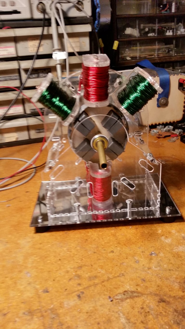
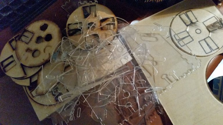
Moving along slower than I would like, because of having to tend to other things. The generator AND the motor coils have been constructed and wound. I have had to recut and redesign here and there, and already have a better redesign idea I may do when done with building this one.
I am ultimatly hoping to come up with a solid kit that I could offer to sell to help others doing this research too, or even just for an interesting science fair model. By selling these kits, Im hoping to help fund my research into new break through energy systems!
Looks like you've taken bedinis "scalar beamer" and are using that for the magnets in the rotor. Using a toothpick on one side to create the tiny gap? The waveform output should look more like what comes out of a 5 bar telephone magneto... with sharp narrow peaks and a wider transition area...
It is his scalar pole concept, but it isn't a "beamer" without a modulating coil. No toothpicks in gaps, all laser cut to be that way. I wanted to use clear poly for the rotor but really not strong enough, and I kept breaking them sliding the magnets in to such tight fits for high speed. I ended up going with thin plywood for the rotor for better strength. I was originally just going to redesign my mini monopole motor for easier experimentation, but then couldn't resist adding all the "bells and whistles" like scalar poles and generator coils. From what I remember John saying, I think the scalar poles are tougher to do with a trigger winding, so may need to do hall switching on this.
Right on, I imagine the waveform has sorta sharp peaks given the compressed fields. Is it all N fields? or are you alternating compressed N's and compressed S's? Hows it run? Looking forward to vids!
They are scalar south poles, and normal north poles, like the normal monopole rotor. But unlike the normal monopole, the north's are longer and the south's are shorter and sharper. Been stuck in the water when it comes to time to move ahead again on this. Next step is to make a timing wheel for the triggers, and then build the circuit.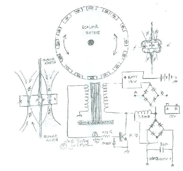 )
)
This is kinda what I'm thinking, where the 1.3Mh coil is the generator coil:
(