Images created by me using LibreCAD.
In this post i would like to share this guide to understand and build the stress matrix for different test used in soil mechanics. I'll explain it in the way i was taughted in my studies, i'm a civil engineering student and i saw this in the subject "Soil Mechanics II". Here we go...
First things first, we must know what is a state of stresses.
A state of stresses is defined as the infinite set of tension vectors that act over the infinite planes that pass through a point at a given moment.
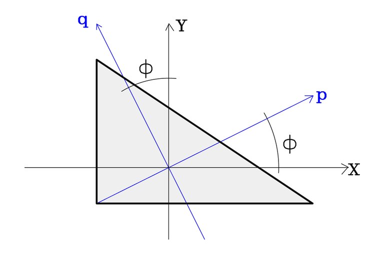
The magnitude of these stresses change by choosing another coordinate system associated with a different orientation. The triangle represents an infinitesimal element on the plane.

For an infinitesimal element on the tri-dimensional space, will act over it a stress state with 9 components. There will be three components of stress acting on each plane: the normal component (the principal) and two shear components. Thus, three stress vectors acts over the infinitesimal element.
In other words, “i” represents the perpendicular axis to the plane in question; and “j” is the axis parallel to said component.
As a result, the stress state for an infinitesimal element is:
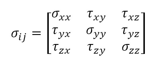
Where the number of columns represents the number of stress vectors (three vectors acting on three planes) and the number of rows stands for the number of components of each vector (two in shear and one normal).
Now we know, it's time to moving forward.
Simple compression test (unidimentional test)
Used to determine the unconfined compression strength in cohesive soils (clays and silts) by application of an axial load. This strength is often denoted “qu” and is the minimum necessary stress to induce the failure in a cylindrical unconfined sample of soil in normalized conditions.

Some interesting thing about this test:
- This test is a particular case of the triaxial test (which we will observe below).
- Delivers a load value for the failure that can be used in projects with no requirement of a more precise value.
- This method can only be applied in cohesive materials that do not expulse water during the test, and maintain their intrinsic strength after removing the confining pressure.
- Shear strength "Su" can be estimated by the ecuation: Su=0,5*qu.
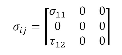
Let's call 1 to the vertical axis, and 2, 3 are the horizontals axes.
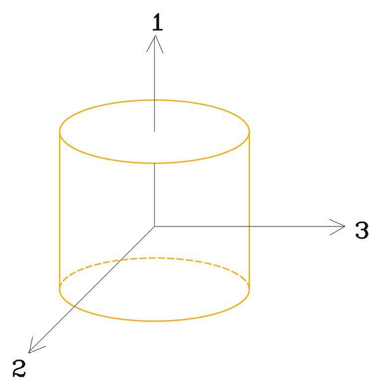
Since there are not confining pressure horizontally, σ22 and σ33 are zero. And σ11 is the principal normal stress in vertical direction, therefore, shear stresses are not existing (i may explain way this happen in another post)
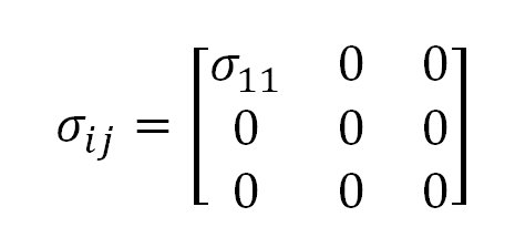
And that is the stress state for this test.
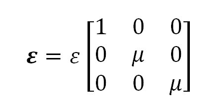
We can describe the deformation too. Obviuosly the sample will suffer a vertical reduction of height, but i guess you already imagine the horizontal deformation of the sample during the test. Thus, we can use the Poisson module "μ" to describe the deformation, by relationing horizontal and vertical strain "ε".

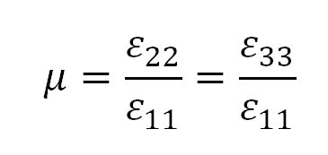
The deformation state for simple compression test is:
Direct shear test
Consist in make slide a portion of soil respect to the other along a predeterminated failure plane by applying a horizontal shear force as a normal load is being applied normal to the motion plane.

There are a normal stress applied vertically (σ11), and a shear force in one of the horizontal directions. Therefore the stress state is shown on the illustration.
Triaxial compression test
The most widely used test to determine the strain-stress characteristics and the strength in all types of soils. The illustration shows the arrangement of the test:
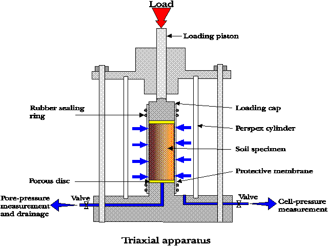
There are two types of triaxial test depending of the behavior of the horizontal stresses:
a) Type I:
Consist in a cylindrical sample of soil subjected to a confining pressure “σ33” which is equal along all surfaces of sample. Then the axial (vertical) stress is increased in “Δσ” until the sample reach the failure (during the whole process horizontal stresses remains constant in all directions, es decir σ22=σ33). Since σ33 and σ11=σ33+Δσ are the principal stresses (major and minor) respectively, there are not shear stresses in the sample. The increment of axial stress “dσ” is defined as “deviator stress” and can be expressed as Δσ=σ11-σ33.
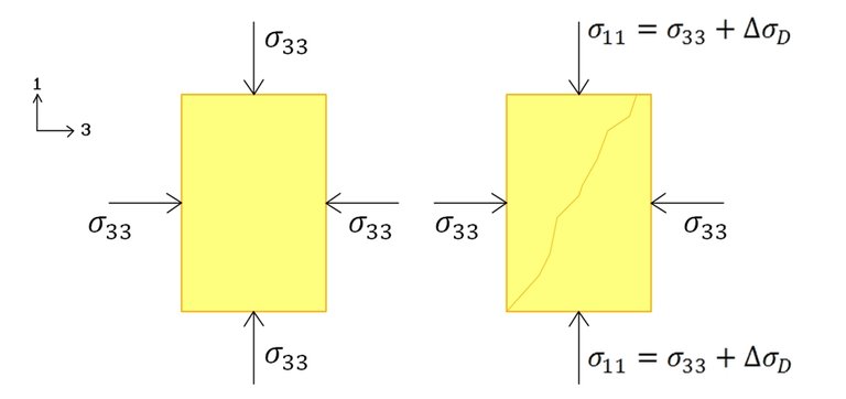
Left: stage one. And right: stage two, The diagonal line represents the failure on the sample.
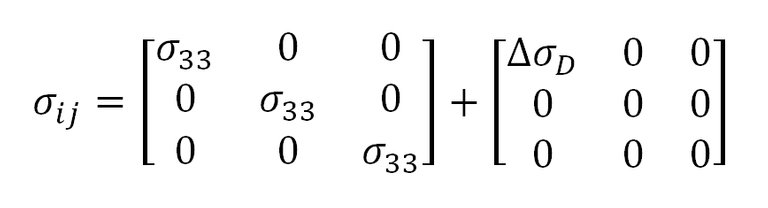
The first matrix represents the first stage of the test, and the second one is when the deviator stress is applied. As a result we obtain the next matrix:
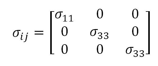
Simple compression test is a particular case of this type of triaxial test.
b) Type II:
In this test the horizontal stress σ33 varying with time, and it exist a lineal relation between horizontal and vertical stresses: σ33= K*σ11, where “K” is the pressure distribution coefficient, which is constant in this type of test. Consequently “K” is zero in Type I triaxial test.
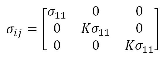
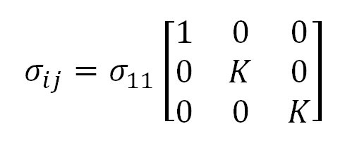
I think you now where the K's coming from.
c) Oedometer Test:
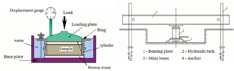
It is actually a particular case of the type II triaxial test. Also denoted as “consolidation test” or “one-dimensional compression test”.
A vertical stress is applied along the vertical axis of the sample while horizontal strains are restricted. The typical arrangement of this test showed in the image below.
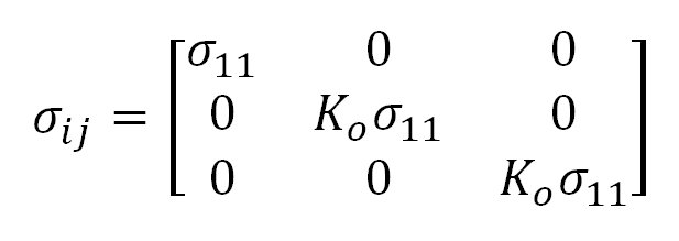
In this test, the relation between lateral and vertical stresses is “Ko”. The stress state for this test is the matrix shown below:
References:
- Das, Braja. Principles of Geotechnical Engineering (2009). Stamfor USA. Cengage Learning
...
Now you know about the stress state or different test. I guess you read it all, analyzed it an might wonder: if the principal stresses are horizontal and vertical, then ¿why the failure is diagonal?... As i say, i'll explain it in a future post.
Thanks for reading.
@acont Civil Engineering Student
Hey there, I was curating your post for steemstem and I noticed that some of the images you used may be protected by copyright and in the references you wrote:
That can't be considered as a source..If you can fix these small things please reply to this comment and I will come back and I will curate you post. Thanks
Hi, thanks for the advice. Just edit the post, and add the source for that images, all of those images were created by me using LibreCAD.
Thanks @aboutcoolscience
Please if you have some time check this article written by me too Tensegrity Structures
There is spanish-speaking room in the discord server of steemstem, I would advise you to have a look and to connect with other spanish-speaking people: https://discord.gg/Kb3zRhV
Thanks again, i will take a look.