
RESISTOR CALCULATIONS
CALCULATE THOSE RESISTORS
Hello gang and welcome to a continuation of the last post i made on resistors. But if you missed it i suggest you read the Resistor basics that was my last post.
Anyways from the last post we see importance of resistors that is essentially limiting current and voltage to different parts of a given circuit.
WHY BOTHER ?!!
.jpeg)
I know guys there are millions of resistor calculators online. In fact there are apps for the purpose. I mean i went on the android store today looking for this calculators and yeah i found a lot. They even came with better functions like value calculators for other components like capacitors and inductors and even for timer circuits. But like i always say you need to know the basis or else you will continue to guess and rely on an app that would not allow flexibility in your calculations. I mean think of it those who wrote the codes for the calculators. Even they needed to know the basics which you are about to learn. This they then used to make this calculators to be even smarter and better and also the calculation are very easy.
For any clarifications needed i encourage questions to be asked in the comments section below and also i will leave links for my references used
Lets get started
RESISTORS IN SERIES AND PARALLEL AND COMBINATIONAL CIRCUITS
When building a circuit you would likely come across resistors connected in series or in parallel. And most times you would find out that would need to connect resistors in such a way to get a resultant resistance equal to that which you are looking for. The two common types of resistor connection include connections in series or in parallel or both.
RESISTORS IN SERIES
.png)
Resistors are said to be connected in series when they are arranged in such a way that its forms a kind of closed loop where there is no breakage in connection . A very common way to look at it is saying that the resistors are connected in a straight line. It is known as a common current circuit.
That is ,
I = I¹ = I² = I³
And the total voltage is
V = V¹ + V² + V³
please do note that the above doesn't mean to the power of 1,2 or 3 it is just to illustrate various currents in a given series circuit
I hope we all remember the famous ohms law. I kinda talked about that here. But for the purpose if this the ohms law us given as V=IR, and putting this in the equation above we have that
IR=IR¹ + IR² + IR³
Now multiplying the above equation by 1/I, we have the new expression as
R = R¹ + R² + R³
This equation above gives the main total resistance in a given series circuit having R¹,R² and R³.
fun fact : this same principal is one that is used when adding two batteries together to get a resultant voltage that has the same current output but doubles or increases in output voltage
RESISTORS IN PARALLEL
.png)
We have just treated the resistors in series and now we go to the next connection type and that is resistors in parallel. This type of connection is said to occur when there are two or more paths for electricity to flow in a given circuit such that if there was a break in connection there will still be a continuous flow of voltage to other parts of the circuit. Think of it as having a stream of water flowing in a given place and there a different branches used to channel water from the flowing river to other parts like to a small farm.
This type of connection is usually called the constant voltage circuit.
fun fact: cells or batteries are usually connected in parallel to create a resultant that has a constant voltage but higher or in some cases double current source
From the above we can see that if it is a constant voltage circuit
V = V¹ = V² = V³
And also we see that since the current isn't constant we have that the total current is given as
I = + I¹ + I² + I³
Note that from the same ohms law we can also have that V=IR(ohms law) and thus we see that the equation changes to I = V/R. Now we substitute into the equation above and it gives:
V/R = V/R¹ + V/R² + V/R³
Multiplying through by 1/V we have that the resultant circuit becomes
1/R = 1/R¹ + 1/R² + 1/R³
Also i want us to know that there is a formula that gives the resultant usually when there are 2 resistors and it is given as
R = R¹ * R²/R¹ + R²
Now that we have settled the parallel and series circuit we can now move to combinational circuits
COMBINATIONAL CIRCUITS
.png)
This circuits are loved by all and commonly used for the singular reason that it combines both the advantage of the parallel and series connection to give a more optimal circuit
The thing is unlike the other circuit types that make use of a general formula that magically helps us to resolve them. Combinational circuits makes use of the knowledge of both circuits to make for the resolution of these circuits
Thus generally to solve combinational circuits we have to:
- Resolve the parallel side of the circuits. To know a parallel connection you will notice that the head or tail of the resistors are joined together by a common node and there will be a path for current to take along the line connecting them.
- Resolving the series part of the circuit. To know the series part you will observe that the tail of one resistor is connected to the head of the other. Also you will notice no breakage along the path connecting them to one another.
i know this thing of head or tails in a resistor is kinda confusing given that as we know the resistor has no polarity or positive and negative point but we can assume that if it is connected in such a way that it connects two different circuits, that is it acts as a bridge between two circuits it is in series and the head is a point that serves to bring current or voltage into a circuit and a tail tends to ground or earth or takes it away from the circuit
VOLTAGE DIVIDER
Well this also an important one. I know i didn't mention it at the beginning but i have to now.
So voltage division is simply an application of the series connection of a circuit that is it help to get different sets of small voltages from a large voltage source at different sections of the resistor circuit. Yeah i know one would say but @chitrics i can do that with a given potentiometer remember what i said. The purpose of this learning is to know the basics and also what about when you don't have a potentiometer or variable resistor plus the potentiometer and the rest are practical applications of the rule you are about to learn.
So assuming you have a network of 2 resistors connected in series and you want to get a say 5volts from a 12volts supply the formula to use and calculate the output voltage at each part is given as
Vout = (Vin / R¹ * R²) * R¹
This is gives the voltage that exists at the resistor R¹. Note that you can also calculate the voltage at R² by multiplying the above by R² and not R¹. Also this can be applied for other resistor circuits that is one with multiple resistors to get this you can use the general form,
Vout = (Vin / the sum of the resistors in the series circuit) * the desired resistor whose voltage is to be calculated
And its as simple as that. I know guys its typical in this series to at least take some questions on all types of the connections so as to demonstrate and yes i will take them
CALCULATIONS
combinational circuits
We will make use a combinational circuit to try and analyze the use of both the series and parallel circuit.
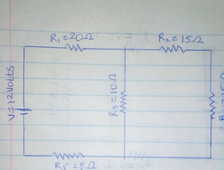
Taking the example above we have that R1 = 20ohms R2 = 15ohms R3 = 20ohms R4 = 15ohms and R5 = 8ohms.
We are then asked to calculate the resultant resistance and also the current flowing in the resultant circuit
Now from the above we see that R4 and R2 are connected in series thus we have that the total resistance
R6 = R2 + R4
This giving us the total resistance to be 30ohms and the new circuit is given as shown below.
.jpg)
Also from this new circuit we have that R6 and R3 are in parallel thus using the relation for parallel circuits we have that
R8 = R6R3/R6+R3*
This gives a new resistance of R8 to be 12ohms. And as usual the new circuit is given below.
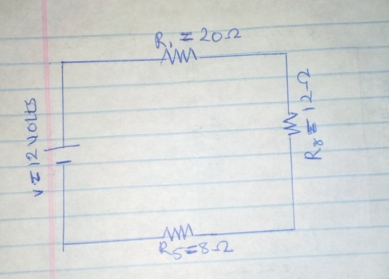
We also have that the three resistors R1, R8 and R5 are connected in series that is they form a closed loop that allows voltage to travel from the positive to the negative without any breakage in connection and then using the general series formula we have that the resultant resistance is given as
.Rt = R1 + R5 + R8
Giving us a resultant of Rt = 40ohms this then leads us to a reduced circuit given below.
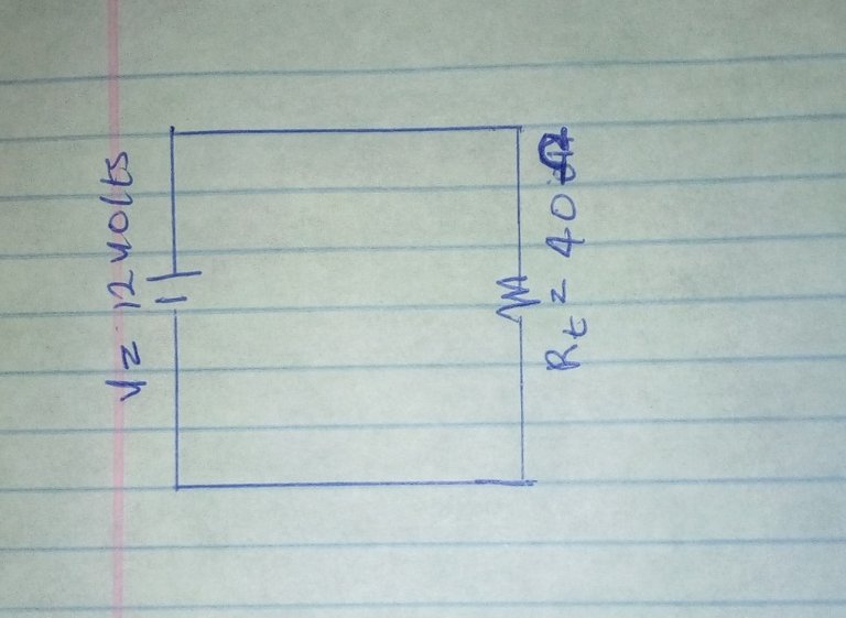
Now it is easy for us to find the total current by applying ohms law to the circuit above we get that
I = V/Rt
That gives a total current of about 0.3 amperes.
For other great and fun examples can be gotten from here. Lets move on to another example but this is on voltage dividers and how to calculate them
VOLTAGE DIVIDERS
A voltage source is given as below its has three resistors of about R1 = 50ohms R2 = 60ohms and R3 = 70ohms. We are then asked to find the voltage at the point R1.
We then have that the formula.
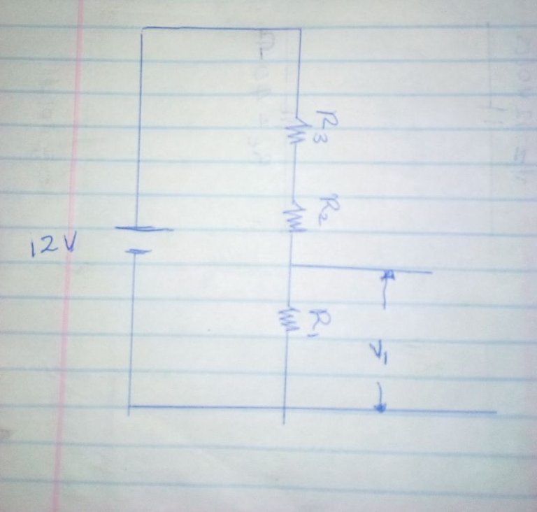
Vout = (Vin/R1+R2+R3)R1*
We then have that the voltage across there is given as 3.33volts
We see how easy it is now i want you guys to try other fun circuits and see what you find
I would also like to point out that in a power supply application it is not advised to use a voltage divider such as a network of resistors or even a potentiometer this is because some times these material do not and cannot resist high current and are not built for fluctuations in supply and so on thus it is advised that you do not use it when you in a power circuit instead use a switching supply or a voltage regulator designed for just this purpose
Anyways as always i would like to hear from you guys in the comments section below. Also be sure to give this post an upvote.
STAY CREATIVE AND I WILL SEE YOU NEXT TIME
Sources : The image for all the pictures were gotten from google images except the pictures in the example section
also the resources used were :
https://en.m.wikipedia.org/wiki/Current_divider
https://learn.sparkfun.com/tutorials/voltage-dividers
http://www.learningaboutelectronics.com/Articles/Current-divider-circuit.php

Congratulations @chitrics! You have completed some achievement on Steemit and have been rewarded with new badge(s) :
Click on any badge to view your own Board of Honor on SteemitBoard.
For more information about SteemitBoard, click here
If you no longer want to receive notifications, reply to this comment with the word
STOP