In high power lasers, pump diode[1], pump combiner [2], [3] and double-clad gain fibers are used. Pump combiners in high power laser systems, aims to unite more than one pump port to first cladding of the double-clad gain fibers and signal port to core part of the double-clad [4] gain fibers.
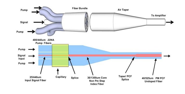
In this post, 6 + 1 pump and signal combiner were built. The following steps have been carried out for the manufacture of the pump and signal combiner.
=> An empty tube which is close to the refractive index of the pump fibers is taken. Due to that by placing the signals and pumps inside the tube and all tapering processes [3] should be done through the tube, the melting temperature of the tube must be close with the melting temperatures of the fibers. A glass tube of 0.22 NA was selected.
=> A fluorine-doped glass tube was selected for the pump and the signal combiner which have a outer diameter of 1100μm and an inner diameter of 800μm. The reason of the these diameters is that these are the smallest diameter that can combine 6 pumps and 1 signal fibers (You can think such that one fiber has 250um coating diameter and the minimum configuration of these 7 fibers can be placed in 750um.). However, a larger tube can be taken to the desired diameter by tapering the tube before placing the tubes.
The flourine-doped tube which has a 800um inner diameter and 1100um outer diameter.
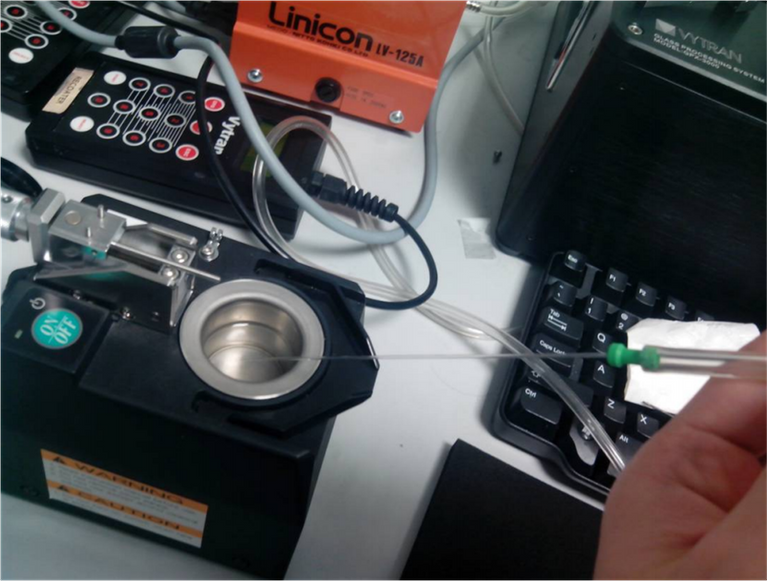
=> The tapering process is done by giving some heat the tube and the tube starts to melt. According to your parameter you can taper it by back and forth the heat block which covers the 2-3 cm of the tube.
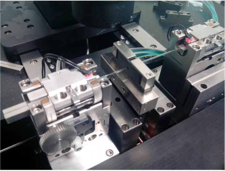
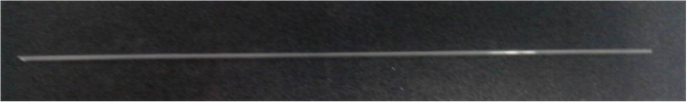
Tapering process of flourine-doped glass tube by VYTRAN galss processor
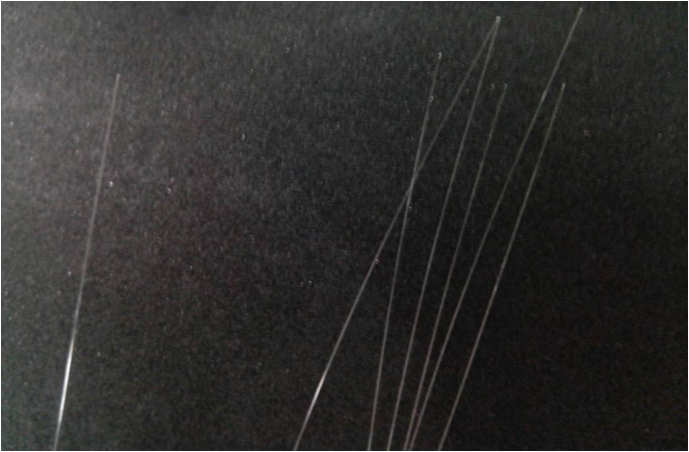
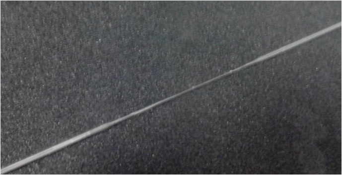
The tapered flourine-doped glass tube
=> The inside of the tube is cleaned thoroughly. The reason is that the tapering process should be done after inserting the fibers inside the tube. That is, if you keep any waste in the inside of the tube in the tapering process, this can damage both the refractive index of the tube (the transmission loss will be huge) and damage the fibers due the burning of the waste. The cleaning process can easily be done with propanol (%99 alcohol). The propanol is sucked by a simple vacuum system into the tube and wait to dry.
Cleaning the flourine-doped glass tube by propanol
=> The coating parts of the signal and pump fibers stripped by a stripper and clean with a peeler Because of the nature of the coating part which only protects against environmental influences, it is made by silicone and causes burning in the process of tapering. The purpose of cleaning is to reduce the contamination to the minimum and thus to get rid of burning that may occur during tapering process or mechanical problems. The length of the stripped part is several centimeters longer than the area to be tapered part. It is necessary to protect the coating part which can be burnt while the tapering process.
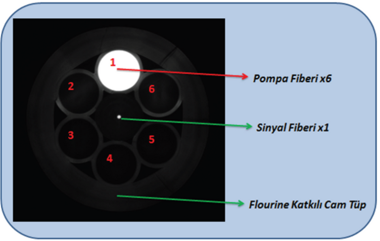
=> The fibers will be collected as the signal fiber is in the middle and the pump fibers (Fig. 3.6) will be around, and those fibers will be aligned and placed in the tube. It is necessary to make sure that the signal is in the middle during placement. If the signal fiber is not centered, the signal transmission is not performed in the desired manner Since the fiber which will be coupled to this tapered and filled tube, has a core exactly in the middle.
Stripped out the coating parts of the 6 pump and one signal fibers
Placing the 6 pump and one signal fibers into the glass tube
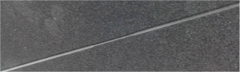
=> Tube, which has seven fibers (one signal fiber and six pump fibers) inside itself tapering process is carried out together with the fibers. You can do this tapering process in many ways. It is important to taper the tube in a homogeneous process. When the tube is thinned, there is no definite subtlety. There must be a constant diameter tapered part and that part must have a similar diameter as gain fiber such as 125um. This constant tapered part must be at least 2-3cm to cleave the fibers at a zero angle. After splicing this combiner and the gain fiber, the pump and signal are transmitted into the same fiber.
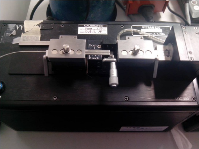
The cleaving process by VYTRAN to an angle "0"
=> The splicing [5] between tapered tube which contains six pump fibers and one signal fiber in the center and double clad fibers is very critical. The first critical point is loss. Both the signal and the pump will not be transmitted with a high efficiency if the proper splicing is not done correctly. Commercially, this splicing losses are about 10% for both. Another critical point is that the signal becomes multimode at the moment of splicing. To prevent this, the diameter of the core of the double clad fiber must be chosen compatible with the core size of the tapered tube signal port.
Tip of the signal and pump combiner with a cleaved 0 angle.
If you enjoyed this post, feel free to Upvote, Follow and Resteem.
All images used in this post are my own. You are welcome to use them with credit.
References are contained in Hyperlinks throughout the article. Everything else is my personal work.
Some of photos from my thesis and you can upload it from here.
Have a curious day, Steemians...
Greetings from Poland!
Greetings from TURKEY...
This post has received a 0.09 % upvote from @drotto thanks to: @banjo.
thanks to @banjo...
Which word did I spell incorrectly?