Here begins a new series of posts I'd like to do on different basic electrical components and how they work. I'll begin with the relay, a type of electric on/off switch.
The reason I'm starting with the relay instead of more basic components is because I have at least one mini-project coming up involving relays and want to cover some of the background here.
The most basic relay is an electromechanical device that lets you turn a switch on or off using electricity. A relay is sort of like a magnetic mechanical "transistor" (kind of...).
Relays: What They Do
The most simple relay is a moderately sized black box (usually a few centimeters across) with four pins. The electrical schematic symbol usually looks like this:

Four-pin relay schematic symbol
Credit
Before I cover how relays work, let's look at what they actually do. When a relay is off and unplugged from any circuit, the four pins will be in their default states. Two of the pins will be connected via a moderately low resistance. These pins are connected to an activation coil, and will be used to operate the switch. The other two pins will be totally disconnected from each other, with infinite resistance (an air gap).
If you apply a high enough voltage (usually 12 volts or so) to the two connected pins, the other two pins that were previously disconnected will suddenly short together, with very little electrical resistance between them. When the first two pins are powered, the other two pins act like a single wire. This means that by powering on the activation pins, you can use the relay as a switch. However, rather than pressing a button or flipping a lever to open and close the switch, this switch is opened and closed by pulses of electric current.
That means that a relay can be used to turn circuits on and off without a human ever physically interacting with the circuit.
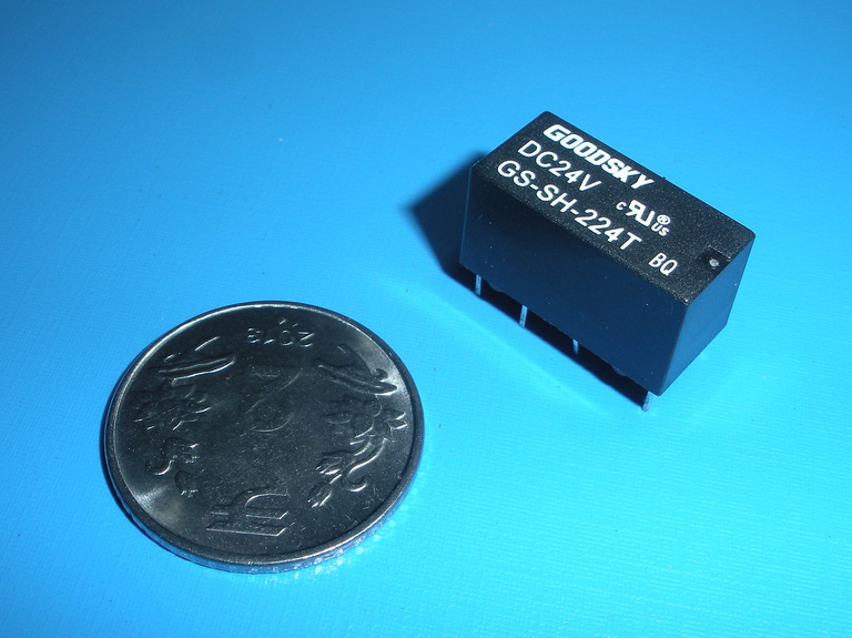
Relays will often look something like this, and are somewhat large for electrical components. You can identify in circuits by looking for plastic, opaque black or grey boxes with four or five pins.
Credit
Another type of simple relay will have five pins: Two activation pins, and three switching pins. One of the switching pins will be always connected to one (and only one) of the other two pins. Exactly which pin is connected to which is determined by whether or not you are powering the two activation pins.
Now that we know what relays do, let's see how they work.
The Electromagnet
As I'm sure many of us have done (either in high school or on our own), you can make a simple electromagnet in a few minutes by winding a bunch of copper wire around a steel bolt. Hook up the wires to the ends of the battery and your new electromagnet will pick up paperclips or nails: A simple analogy for a permanent magnet that can be turned on and off at will.
The way this magnet works is pretty simple. When you wind wire into a cylindrical coil and then run electrical current through it, a magnetic field will be formed inside and around the wire. Inside the coil itself, the magnetic field will be mostly parallel to the coil. Place a "magnetic" material like iron in the center of the coil, and the magnetic dipoles of electrons in the material will line up with the parallel field, amplifying the field in the center of the coil. This then lets you magnetize other objects (like paperclips) and pick them up.
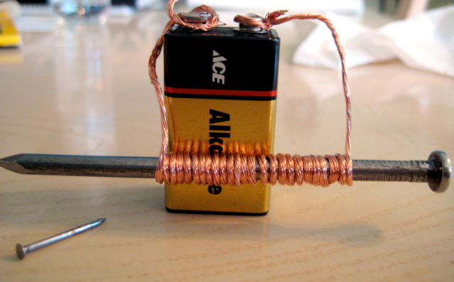
Simple homemade electromagnet
Credit
It is a similar electromagnet (called an inductor) that lies hidden behind the two activation pins of a relay. Inside the relay is a small coil of wire wrapped around an iron-containing core, just like the bolt electromagnet from before. Power it up and a magnetic field forms inside the coil.
Inside a Relay
This inductor can be used to create an electric switch - the relay.
Within a relay, a strip of metal is placed and wired out of the relay, forming one of the pins. If this is a four pin relay, this metal won't be touching the other switching pin. If it's a five pin relay, the metal will be in contact with one of the two switching pins, shorting the two together. The metal strip is made out of a material that reacts well to magnet fields, like iron.
Power up the inductor and a magnetic field forms, amplified by the core. This core is very close to the strip, so when the inductor is turned on (by running current through the relay's activation pins), the field around the metal strip is somewhat high. This magnetizes the strip, causing it to be pulled into the inductor by a magnetic force.
So, when the coil is powered on, the metal strip flies toward the coil. This causes it to contact another piece of metal, connecting to the other switching pin! Now, the two pins are electrically connected, and they are shorted together. For the four pin relay, this means that the switch is now "ON", and electricity can flow across the switching pins. For the five pin relay, this means that the the middle pin will detach from one of the outer pins and short with the other outer pin.
In this way, a relay can turn any electric circuit on and off using nothing but another electric signal. All of this is made possible by an interaction between the magnetic inductor and a physical, mechanical switch. Really, a relay is not fundamentally different than building an electromagnet out of a bolt and picking up paperclips. The only difference is that relays look nicer and come in smaller, more reliable packages.
Uses for Relays
Relays can be used anywhere a switch is used. For example, you could use one to turn on your flashlight, or turn off a TV. Using a relay directly in place of a physical switch isn't usually that useful, but if you need a circuit to react to another circuit, relays become incredibly useful.
Say for example that you need a light to come on any time your computer is plugged in. A DIY circuit could utilize a relay to do just this, by powering on the relay when the computer draws current from the wall. This also illustrates a key advantage of relays over physical switches: Relays allow something (or someone) to interact with a high voltage circuit without ever coming into contact with anything touching the high voltage circuit.
Say I wanted to build a new stun gun, but I for some reason decided to use deadly amounts of current at thousands of volts on the output arc. You could just use a physical button to turn on the circuit, but what if something went wrong? Say I did a really bad job of putting safety precautions into circuit and the button's frame was somehow electrified to the high voltage output. The next person to press the on button is now toast. Even if something like this was (easily) avoided, it would probably be best if you never had to actually touch anything that was connected to the high voltage circuit, even if it was only connected to the low voltage side.
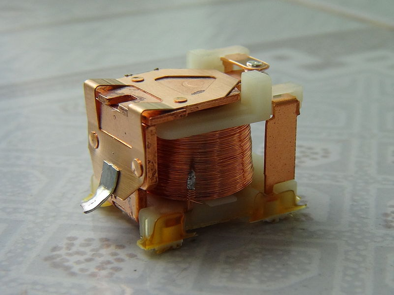
The guts of a relay
Credit
A relay solves this problem. Using a relay, you can now turn on the stun gun using a low, harmless voltage powering the relay's inductor coil. Now, nothing you touch ever physically touches anything connected to any part of the high voltage circuit (power, output, or both). This is honestly a pretty bad example due to how simple it would be to safe a stun gun, but I hope it illustrates the point that having a circuit isolated from another circuit, but still able to interact with the other circuit, is a benefit.
Relays can also be used to make simple oscillators (that is, a DC direct-current to AC alternating-current converter). By running the power line (that powers the activation pins) through two of the other pins, the relay will oscillate, allowing things like LED flashers to be built with just a few components.
You'll usually find relays in higher power applications. If you ever come across some taking apart junk electronics, I recommend you keep them as they are useful and worth more than many smaller components. You can even take them out and obtain a ton of very thin magnet wire for other uses.
Glad to see you made it to the end. Let me know if you have any questions or comments, or if I got something wrong. I recently found some schematics online for simple relay-driven radio jammers/transmitters, and I'd like to make one when I get the chance with some modifications, so keep an eye out for a post on that sometime (hopefully) soon.
Thanks for reading!
Additional Reading:
Circuits Today: How Relays Work
I look forward to this series @proteus-h! Btw what do you make of this? I've got a few of these (actually dads).
Another view, a relay type device from the Vacuum tube era?...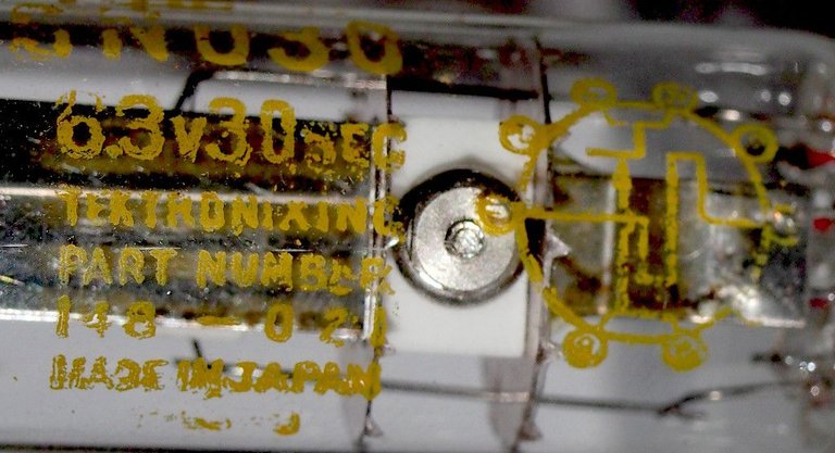
Strange device - Unless there's a coil in there I don't think its a relay because I don't see a reason to do so in a vacuum. Maybe some kind of tetrode?
The only thing similar device I could find online is a heat actuated relay, so like a bimetallic strip inside. Note there is no getter in this tube, which means no requirement for a vacuum. They used to flash Caesium or Barium metal onto the inside to collect impurities/moisture. Thanks for having a look @proteus-h
Actually that would make sense if it was heat activated! The vacuum would prevent any convection/conduction so the metal would heat up to much higher temperatures with only EM radiation as a way to remove heat from the strip. That would make it way easier to heat the device up enough for thermal expansion to activate the relay.
Pretty cool if that's the case, I've never heard of a device like this I know some temperature gauges use this principle, but I've never seen a relay like that prior to now. It's possible that they left out the getter and it's just a low vacuum, which would work fine for something like this.
Nice article. Keep up the good work.
I have one thing about using relays as LED switches/flashes. If you will use a relay (not SSR one) as the LED switch, then it will get worn out faster, as it's mechanical device.
A transistor is definitely a better option for long term LED flashing. However, a relay can still be used for this, especially if it is made to oscillate at a low frequency.
Of course your are right, I just wanted to point that out, as I destroyed one of relays by rapid LED flashing(about 100Hz), so you won't make similar mistake as me.
Exactly what I need. I really miss some knowledge in the electrical engineering field. Thanks @proteus-h!
Nice & keep up good work!
Awesome!!!!
All pics sorted:)
Thank you @proteus-h
Next, how to add an additional layer of protection with the use of optocoupler and transistor to protect driver circuit from noise and spikes.
In nutshell you connect secondary side of optocoupler to gate of the relay, then you use first side of the optocoupler to drive secondary side. (which is now connected to gate of relay)
Can you use this relay in opposite way? For example, when you apply 12V or higher the circuit will be close not short..
Thanks for sharing such a good explanation..
Definitely, and I'm sure relays exist that do this. You would just have to have the default state be the two pins connected, and then when the coil powers on it draws the switch open.
I see, there is a normally open and close connections. You can switch according to your application. Thanks my friend..
Very informative - I just miss the information on what happens when you switch off your inductor coil - the metal somehow needs to get back into its default state. I wonder if the metal itself is somewhat spring-like, or whether a simple spring is used to push it back into its default position?
Most of the ones I've seen contained a discrete spring that connects to the opposite side of moving metal bar and pulls it back to the default position when the magnetic force is removed.
Being A SteemStem Member