A transformer is static piece of apparatus by means of which electric power in one circuit is transformed into electric power in another circuit.
A transformer is an electrical device that transforms an A.C system into another with different voltage and current but the same frequency.
The primary side is connected to the source while secondary side is connected to the load.
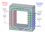
Transformer consists of 2 or control turn more winding i.e. primary & secondary winding. [Also Auto winding]
The winding is connected / interlinked with a common or mutual magnetic field.
There is no electrical connection between the field winding.
There are 2 types of transformer:
Step up transformer: When the secondary voltage greater than the primary voltage [used in transmitting station (16-25 kv)].
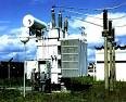
Step down transformer occurs when the secondary voltage is less than primary voltage [Used in distributing station 330kv].
The equipment used in power is machine.
At transmitting level 16-25kv raised to 330kv.
At distributing level 330kv Step down to 33kv or 11kv or 415v or 240v.
Winding transformer
It has two windings.
The primary winding have primary parameters, source primary current (IP), voltage primary (VP) & Primary winding/ turns (NP). The secondary winding also have secondary parameters; secondary current (IS), secondary voltage VS & secondary turns NS.
There are 3 types of transformers.
Core type transformer
Shell type transformer
Berry type transformer
Core type transformer
In this type, half of primary & half of secondary winding are placed round each other limb as seen below.
In this type, it reduces the effect of flux linkage.
Flux linkage effect the operation of the transformer.
The limbs are joined together by iron core/ iron stoke. We may have 2 core also in 3 phase (winding) transformer.
Advantages of core type transformer.
It can be repaired easily . It permits easy inspection. To know types of
In the shell type, both winding are placed round the central limb. The outer limb is used (acting) as a low reluctance flux path. We can also have this type of arrangement in 3-phase transformer.
Characteristics of shell type
It is more robust mechanically since the areas are more readily broad. In this type of construction, the core is considered to be placed around the winding.
Difference between berry & shell type transformer
The magnetic part is distributed equally round the winding in the berry type due to constructional difficulties, this type is not so common as the shell & core type of transformer.
Equivalent circuit for the transformer
In a typical transformer, the permeability is not infinite.
Winding resistance is present back copper wire have resistance.
Losses occur in iron core & due to this losses iron core, we have losses in transformer.
The flux linkage between the winding is not 100% (some will escape through primary side.)
Ip=Io+Ip
Io=Ic + Im
Transformer Equipment Circuit
RC is the core less
Xm is magnetizing loss component
Vp & Vs are both Primary & Secondary voltage
In transformer, the frequency at the source equals the frequency at the frequency at the load end. When there is no load at the secondary, the secondary voltage is zero & also current will be zero.
Therefore, Is=0, Ip=0; at no load station.
Phase diagram [ no load phasor ].
IO =√ Ic2 + I m2
No load power factor can be calculated using SOHCAHTOA i.e. cosɵ = IC / I0.
Summary, under load condition IP will be equal to I0 + Ip’.
Also the Ip will not equal zero & Is also will not equal zero i.e. Ip’≠0, Is ≠0.
Phasor diagram for on load condition.
Өs & Ө0 are the power factor for primary (Өs) and secondary winding.
Cos Өp = Power factor for primary winding.
Cos Өs =
A shunt generator has a full load current of 196A at 220v. The stray losses are 720 watts & shunt field coil resistance is 55 ohm. It has will load efficiency of 88%. Find the armature resistance also find the load current corresponding to the maximum efficient.
Solution
Load current = 196A Full load efficiency= 80%
Output = 220v Armature resistance =?
Stray losses = 720 watts Full load current =?
Shunt field resistance = 55 ohms
Power factor (P) = 1v
= 196×220 = 43120watts.
Efficiency = Output Power/Input Power
= Power output + total losses
Input power = 43120/0.88 = 49,000watts
Since power input = Power Output + total loss
Total loss = 49000-43120
= 5880 watts
Since Total loss = I2Ra + Stray loss + I2shRsh
= (I + Ish)2Ra + Stray loss + I2shRsh
Ish = 220/55 = 4A
5880 = (196 + 4)2Ra + 720 + (42×55)
= 40000Ra + 1600
Ra = 5880 – 1600÷40000 = 4270/40000 = 0.107ohms
(II) I2Ra = Stray loss = Wc.
I = √(Wc/Ra) = √(1600/0.107) = I = 122.28A
source
[source](https://www.123rf>stock-photo>photo
[source](https://www.canstockphoto.com>transformer
[source](https://www.pinterest.com>electrical transformers
source
source[images.png] source
![images[1][3].jpg](https://images.hive.blog/768x0/https://steemitimages.com/DQmRE2JsDxcyh4THhuv2Pid1RNeG1Zs2o5iLPHN1m6UeYsQ/images%5B1%5D%5B3%5D.jpg)
![images[1][6].jpg](https://images.hive.blog/768x0/https://steemitimages.com/DQmdVCj1d83q6yuTQgtjCrvaLadHFeZogAcZLX9FEwuf57i/images%5B1%5D%5B6%5D.jpg)
![images[1][8].jpg](https://images.hive.blog/768x0/https://steemitimages.com/DQmWDeotqBmTDjHicJymk4YfUATNtYeZYsiuitDwA1qASaU/images%5B1%5D%5B8%5D.jpg)
Those lessons are the misery of my engineering life
Thanks for the word of encouragement.