The water management is vital in the serious developing modern societies, due to the implememtation of water availability requirements (for residential and/or agricultural use). In such applications, it is required to monitor the level of water contained in small to large-scale storage tanks of water distribution networks.
Liquid storage tanks are an essential part of vital operations in various industrial applications. The determination of liquid level applications has been developed for many years especially for process industries. Sensors suitable for monitoring the level of many different kinds of liquids are currently available, such as short or long-range sensors for hazardous or nonhazardous liquids, exhibiting a variety of resolution and accuracy performances .
An ideal liquid level sensing system should be able to feature stability, high resolution and be of low cost. Due to the typically large number of water storage tanks contained in water distribution networks (e.g. in communities, cities, etc.), a high number of water level data-acquisition systems must be installed within the water distribution system, in order to obtain accurate information of water availability. The collection of data from water level tanks is essential for applying appropriate water management schemes. Thus, long-range, easy to install and low cost water level sensors are required to monitor this vast amount of water tanks.
Liquid measurement systems determine the position of the liquid surface level relative to the top or bottom of the process fluid storage vessel. Liquid level in a container can be measured by several methods. The perfect level technology that works for every liquid level and point level application does not exist.
Selected method for liquid level measurement depends on a number of factors, such as:
• The type of container holding the liquid (i.e. open or close tank),
• Characteristics of the fluid (the number of phases in the liquid and its material properties)
• Process conditions.
Depending upon the above factors, a number of different level measurement techniques can be used. These include sight glass, floats, differential pressure gauges, float switches, magnetic switches, magnetic level gauges, displacers, load cells, capacitance probes, laser level transmitters, radar level transmitters, and ultrasonic transducers, etc. The selection of a single or multiple of the above-mentioned techniques can be utilized to measure the liquid level. Where high precision is required, multiple techniques are utilized together to achieve this accuracy (Hambrice and Hopper, 2004).
From the above-mentioned techniques, ultrasonic, radar and laser are among the most advanced technologies, requiring advanced and sophisticated computer intelligence; and thus by combining these with advanced communication capabilities and digital calibration schemes, the trend toward embedding microprocessor based computers in virtually all level measurement products can be explained (Hambrice and Hopper, 2004).
Ultrasonic level transducers measures the distance between the liquid surface and the transducer using the time required for the ultrasonic pulse to travel back and forth from the liquid surface.
some of the advantages of using ultrasonic liquid level measurement include:
i. Low power consumption
ii. Low computational effort required to configure
iii. Low purchase prices
iv. Measurement not affected by density changes, dielectric or conductivity of the material under measurement
v. No moving parts thus requires no or little maintenance
vi. Suitable for applications requiring high hygiene levels
vii. Requires no calibration with change in medium
Use of water reservoirs (overhead tanks) to store water and make it available at times of shortage is common. Available methods for controlling the volume of water accurately to prevent overflow (wastage) and under fills are expensive and not efficient. Some of these available methods also corrode when in contact with water vapor thus compromising on hygiene. Therefore an accurate, cost effective, water resistant and most importantly hygienic method for monitoring and control of water level is required , hence this study.
Based on price, accuracy, appearance, response rate, ease of calibration or programming, and non- intrusive level measurement, ultrasonic level measurement is selected for an accurate and cost effective liquid level measurement and control.
Contribution to Knowledge
This study will design and develop an accurate and cost effective water volume monitoring and control system.
Ultrasonic Measurement Techniques
Ultrasonic measurement technique can be used to measure liquid levels. Ultrasonic sensors are utilized for many measurement purposes, such as for non-destructive testing (NDT), thickness gauging, level measurements, concentration and density measurements, flow measurements, or interface level measurements.
An ultrasonic transducer converts an electrical signal into an ultrasonic wave and vice versa. As such, they transmit acoustic waves and receive them back. Ultrasonic sensors cannot be used alone. For an efficient use of such sensor, well-developed transmitter and receiver electronics circuitry are necessary. A single transducer can be utilized for both transmitting and receiving purposes. In some cases, separate transmitting and receiving transducers are also utilized. An intelligent ultrasonic sensor systems work is not only to detect the received signal but to also extract the information carried in the received signal.
Ultrasound
Waves exist as either electromechanical of magnetic waves. While electromagnetic waves can be transmitted through a vacuum, mechanical waves require a medium to propagate. Sound is a typical example of a mechanical wave. Ultrasound is basically sound waves with frequency above the range of human hearing. While human hearing ranges from 20 to 20 KHz, ultrasonic sound is normally above 20 kHz (Bruneau et al., 2006). Ultrasound can propagate through all media including solid liquids and gasses except vacuum (Ihara, 2002). It propagates through the medium, in finite time as mechanical sound waves by the vibration of the molecules or atoms of the medium or any particles present (elastic wave). Ultrasonic waves can be propagated as
Longitudinal waves (media particle motion in the same direction as propagation of wave)
Share wave (particle motion perpendicular to direction of wave propagation)
Surface wave (particle motion is elliptical with velocity approximately one wave length)
Plate or lamb waves (complex vibrations in materials whose thickness is less than wave length of ultrasound wave incident on it).
As the sound waves travel through the air, they produce vibrations in the air particles which change the pressure and density of the air particles along the direction of the wave. If the source of sound wave vibrates in a sinusoidal manner, the pressure vibrations will also be sinusoidal. In a continuous medium, the behavior of ultrasonic waves is closely related to a balance between the forces of inertia and elastic deformation (Ihara, 2013). Ultrasonic wave impart motion to the material when it propagates. This is referred to as particle motion. The balance between inertia and elasticity develops into a linear relationship between stress σ and particle velocity v, σ=zv the proportional factor z is the specific acoustic impedance of an ultrasonic wave.
z=σ/v=ρc (Ihara, 2013) (2.1)
Where
ρ is the density of the propagating medium
c is the ultrasound wave velocity
Existing Methods of Liquid Level Detection Using Ultrasound
Schnake (2006) categorized devices available for level measurement into continuous level measurement devices (which measure the continuous liquid level in a reservoir), or a point level measurement device that measures liquid level at one or more points in a tank. Continuous measurement is utilized when it is important to monitor the fluid at all points within a limit for the control of its parameters within a process as is obtainable in industrial process plants. Point level control is used when it is necessary only to determine a high point, low point or intermediate set point in a liquid.
Another method for categorization of measurement methodologies - based on sensor environment interaction- is contact and non-contact (non–invasive) methods (Hall, 1984). Contact sensors must touch their environment to operate and are hence limited to use on those systems that do not pose harm to the sensor. Almost all contact sensors measure one of the three different physical quantities: force, proximity and slip. Non-contact sensors comprise six groups according to principles of operation: optical, magnetic, capacitive, resistive, ultrasound and air pressure.
Marko et al. (2006) developed an ultrasound level detecting system that made use of an electronic oscillator to drive an ultrasonic transmitter. The control electronics generates a package of voltage impulses at the frequency of 40Hz and then feeds this into the ultrasonic transmitter. The transmitted ultrasonic impulse then reflects from the surface of the liquid or tender material in the container back to the receiver which converts the pulse back to a voltage signal. The oscilloscope also drives a counter and its path is such that the receiver’s input when amplified is used to disconnect the oscilloscope from the counter. The oscilloscope’s frequency is set to 7 kHz. This frequency represents half of acoustic velocity which at air temperature of 20oC amounts to 343.8 m/s. Since the sound must cross a double distance from transmitter to receiver, the actual length is obtained by dividing acoustic velocity value by two which amount to 171.9m/s. The number of impulses registered by the counter – as arriving from the oscilloscope is proportional with the distance between the device and the level in the container.
Lichte (2006) described a fluid volume measurement system, where an ultrasonic sensor is mounted at the bottom of the tank. Echo pulses are transmitted from the sensor and travel through the fluid and are reflected back from a reflective float placed at the surface of the liquid. The time taken for the wave to propagate and return back to the transducer is utilized to determine the volume of the liquid.
Cryton et al. (1998) described a measuring system that determined the height of liquid contained in a storage tank. A tube is placed inside a tank which contains a float that is buoyed on the surface of the liquid. An ultrasonic transmitter is placed inside the tube. The ultrasonic transducer emits ultrasonic pulses detected at the float, receives the reflected ultrasonic pulses and responsively produces an echo signal. The float has a top and bottom section separated by a cylindrical section. The bottom portion includes a spherical surface which receives the ultrasonic pulses. The spherical surface has predetermined radius which is a function of the inside diameter of the tube, the height of the cylindrical portion of the float and the outside diameter of the cylindrical portion of the float. A temperature sensor measures the temperature of the liquid and produces a thermometric signal in response to the liquid temperature. A microprocessor receives the echo and thermometric signals, determines the speed of the ultrasonic pulse travelling in the liquid and responsively determine the liquid height.
Koblasz et al. (1983) described an ultrasound liquid level detection system for automatically controlling the dispensing of a carbonated beverage. The design used microprocessor controlled circuitry for monitoring and implementing the automatic dispensing process. The microprocessor is interfaced with an ultrasonic transducer that transmits ultrasonic waves towards the target container that needs to be filled, detects the reflected ultrasonic waves and then analyses the characteristics of the wave when required. It uses the microprocessor to implement control functions of the automatic dispensing process. The system also has additional safeguards programmed into the microprocessor to preclude operator errors such as triggering of the dispenser system by devises other than the container to be filled.
This study attempt to address the challenges involved in the use of ultrasonic waves for the accurate determination and control of stored water level using efficient and cost effective methodologies and devices.
Ultrasonic generation
The most commonly used material for the generation of ultrasound is the Piezo-electric material (Ivana et al., 2005). According to Sisiliano et al. (2008), two major available transducers available that operate in air and can operate in principle as both a transmitter and a receiver are electrostatic and piezoelectric devices.
Electrostic ultrasound transducers generate sound by the force exerted on a member suspended in an electrostatic field. They consist of a thin flat diaphragm usually consisting of a plastic sheet coated with a conductive material such as graphite sandwiched between two electrically conductive grids with small air gaps between the diaphragm and the grids. Electrostatic devices have higher sensitivity and band width but require higher voltage bias typically above 100v. Hence they have complicated electronic interfaces.
Piezoelectric devices operate based on the ability of certain materials to produce a voltage when subjected to mechanical stress. The effect is reversible such that when an external voltage is applied, the material changes in dimension. The application of mechanical stress on ceramics causes a polarization of the ions of the crystal atoms of the ceramic material thereby resulting in a net electrical charge across the crystal. Several ceramic materials exhibit piezoelectricity. These include lead – zirconate titanate, lead-titanate, lead -zirconate and barium-titanate (James, 2010)
Ultrasound can also be obtained in a similar way to conventional sound waves via a speaker where an electromagnet within the speaker creates a magnetic field when an electrical current flow through its coil. The coil behaves like a permanent magnet but flips the poles of the magnet when the direction of the current in the coil reverses.
2.5 Propagation of Ultrasound
Transmitted ultrasonic sound waves are longitudinal mechanical waves that propagate through a medium at frequency range of 20 kHz to about 1 GHz, and therefore they cannot be heard by human beings. (Pascal 2011).
Mechanical perturbation from the waves causes the tiny medium particles to move from their resting positions. This disturbance induces a displacement of these particles and as one particle moves, it transmits the energy to adjacent particles and ultimately to other parts of the medium.
For technical applications the frequency range from 20 kHz to tens of MHz is very important. For industrial applications the frequency range from 0.5 MHz to 15 MHz is used. Selection of frequency depends upon the application conditions and the accuracy requirements.
According to Hauptmann et al. (1998), the most important advantage of using ultrasonic sensors are the non-invasive and non-intrusiveness of these instruments as the acoustic wave can often penetrate pipes or walls of vessels of a few millimeter thickness.
Ultrasonic frequency for industrial applications is in MHz range. MHz frequency acoustic waves corresponds to very short wavelengths, which helps in non-destructive testing (NDT), as these waves can reflect from very small defects inside the material. Similar to light waves, ultrasonic vibrations travel in the form of waves too, except that they cannot travel in vacuum, whereas light is able to.
Velocity of Ultrasound
The velocity of a sound wave is defined as the rate of transfer of the wave energy through the particle displacement with respect to time. For monochromatic waves, the wavelength is directly proportional to the velocity of the wave and inversely proportional to the frequency of the wave.
The ultrasonic wave needs a medium to travel in, where, c is the velocity of sound in a material and is constant at a given temperature and pressure.
c=fλ
T=1/f
Where,
λ is the wavelength,
c is the material sound velocity,
f is the frequency, and
T is the time period
Characteristics of the material medium ( compressibility and density ) has effect on the velocity and attenuation of ultrasound waves this is due to difference in mass of atomic particles and spring constant for different materials ( Laugier et al., 2011)
If the medium is a liquid or a gas, and has a bulk modulus k and density ρ, speed of sound in that medium or fluid is given as
c=√(K/ρ)
Two basic quantities are monitored in the ultrasonic testing. These are,
(a) the time of flight of sound through the medium, and
(b) the relative change in the amplitude of the received signal.
The first measured quantity, being the time of flight, is the time between the transmission and the receiving of the pulse. Utilizing the time of flight and ultrasonic velocity, material thickness can be calculated as shown in Equation (2.5), (Hauptmann et al., 1998).
d=ct/2 Where,
d is the material thickness,
c is the material sound velocity, and
t is the time of flight.
The second measured quantity, being the relative change in the amplitude of the received signal. This relative change is commonly measured in decibels (dB) values. The dB values are the logarithmic value of the ratio of the two different signals amplitudes. It can be calculated as shown in below, (Joos et al., 1993)
"dB = 20 " log_10〖(A1/A2〗)
Where,
dB is the amplitude ratio in decibels,
A1 is the amplitude of signal 1, and
A2 is the amplitude of signal 2.
Sensitivity of any ultrasonic system is its ability to detect defects in a material at a given depth. The greater the signal received from a reflector, the more sensitive that ultrasonic system is.
Attenuation
The strength of the ultrasonic waves attenuates (diminishes) as it propagates through a medium. The causes of attenuation are diffraction, absorption, and scattering (Laugier et al., 2011) higher frequency ultrasonic waves attenuate more than the low frequency waves. The higher the attenuation rate the shorter the distance is in which the wave reaches. Thus, the amount of attenuation in the medium plays an important role in transducer selection (Hennmg et al., 1994; Vives, 2008; Cowell and Freear, 2008).
Absorption losses in fluid media is mainly due to viscous losses, heat condition losses, and losses associated with internal molecular processes of the fluid (Vetreno, 2007). Scattering is the reflection of the sound in directions other than the initial direction from the source of propagation.
The combined effect of scattering and absorption is called attenuation.
Boundary Characteristics of Ultrasonic Waves
When sound wave is incident on the boundary of different media, a portion of the wave is reflected and a portion is transmitted into the second medium (the transmitted portion also changes the direction of its travel; that is it is refracted) other parts of the originally incident wave are absorbed or diffracted. The technique of utilizing the reflective property of materials and analyzing the reflected sound wave when they bounce of the mediums boundary is known as reflectometry. The sensitivity of the ultrasonic sensor receiver depends on the percentage of the original disbursed sound energy that is successfully reflected back and detected. This can be affected by the principle of reflection, refraction, transmission and wave scattering.
Sound field of ultrasonic waves
The sound field from an ultrasonic transducer can be divided into two zones, the near field and the far field. The region directly in front of the transducer is called the near field (N), where the echo amplitude goes through a series of maxima and minima and ends at a last maxima at a distance N. The near field is also the natural focus of the transducers. Beyond N, the pressure of the sound wave gradually drops to zero and this region is called the far field. The near field distance depends on the diameter of the transducer element, its center frequency, the medium sound velocity, and the wave length. Equation (2.7) shows the formula for calculating the near field distance. (Hennmg et al., 1994).
N=D^2 f/4c
N=D^2/4λ
Where,
N is the near field distance,
D is the element diameter,
f is the frequency,
c is the sound velocity in the medium, and
λ is the wavelength.
Figure 2.1 shows a beam profile for a flat ultrasonic transducer where a red colored region represents an area of high acoustic energy while blue and green represents low energy regions
METHODOLOGY
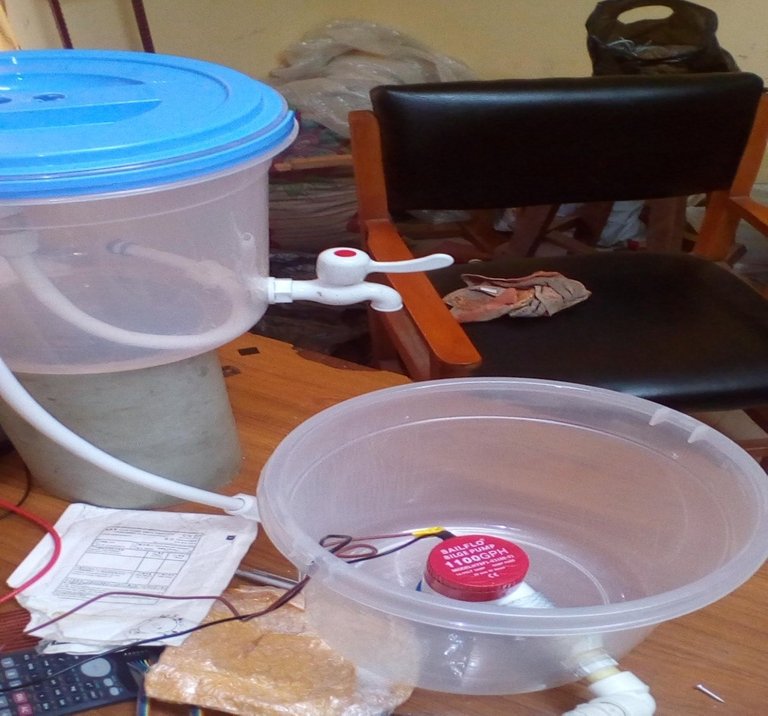
A system to detect the level of water in a reservoir, monitor the water level and control a pump to refill the reservoir as needed was to be developed. The system would make use of:
• an ultrasonic sensor to detect the water level,
• a microprocessor to filter the signals from the sensor, process the corresponding volume of water and subsequently control the feed pump to the reservoir.
• a Liquid Crystal Display (LCD) to show the volume content of the reservoir and the status of the pump.
• A switching control system consisting of electromagnetic switches to drive the high power pump.
Figure 3.1 below shows the block diagram of the system.
Ultrasonic sensor module HC-SR04 is used as the level sensor. It consist of an ultrasonic transmitter, an ultrasonic receiver and a control circuit all in one module. It operates on a Dc voltage of 5V and current of 15ma. It has a minimum range of 2 cm and a maximum range of 406 cm and manufactures accuracy specification of ±3mm. It has four pins (Figure 3.2) namely
VCC – 5V, Positive power supply
TRIG- Trigger Pin
ECHO- Echo Pin
GND- Negative power supply
The sensor is easy to implement and has a compact size of 45 X 20 X 15mm. The transmitter sends a burst of ultrasonic pulse at 40 kHz frequency and waits for the receiver to detect the resulting echo from the surface to be analyzed. It has an on chip microcontroller based circuitry that produces a dc voltage signal at the echo pin whose width is proportional to the to the distance separation of the transducer to the surface under consideration.
The operation, control and data processing of the sensor module are done with a micro controller coupled to it via a four wire bus. The distance information from the ultrasound module is processed by the microcontroller and utilized in the control of the water level in a tank via a pump.
The microcontroller PIC16F877A is a 40 pin RISC architecture microcontroller with operating voltage range of 2.0 to 5.5V and less than 0.6ma current. It can operate over a wide frequency bandwidth of 0 to 20MHZ and temperature range of -55oC to +125oC.
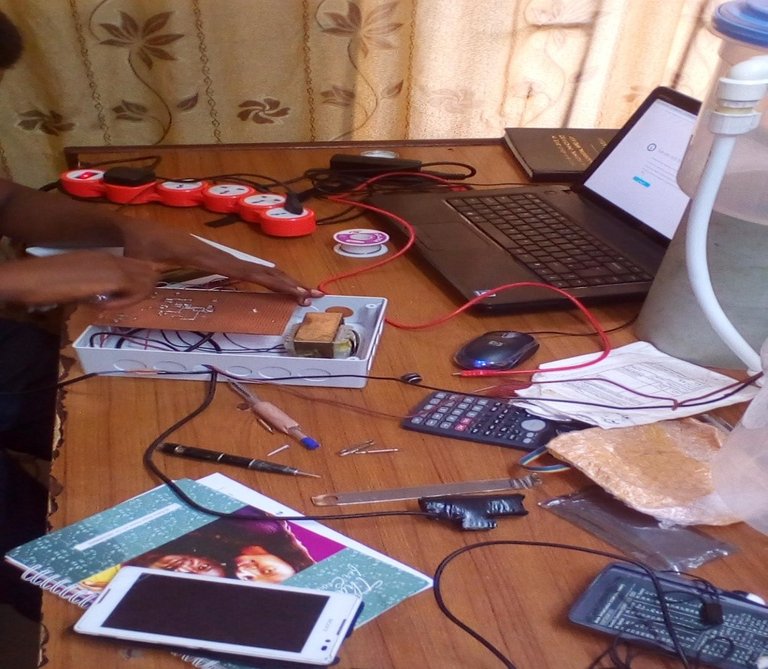
The code for the microcontroller is developed in embedded c programing language. MikroCPro for Pic TM Integrated Development Environment (IDE) is used in writing the code.
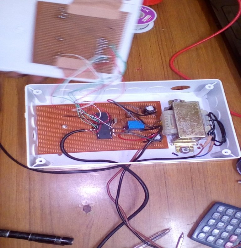
The microcontroller and supporting electronics are housed in a control panel together with the electromagnetic relays for controlling the high current pump. The relays can handle current switch of over 5A at operating voltage of 12v. The microcontroller has a current output of 20 ma which is insufficient to drive the electromagnetic relay or the pump, hence an interface circuit consisting of transistors is used to couple the microcontroller to the relays.
To determine the level of liquid in the container, a train of pulses is generated and transmitted towards the surface of interest and the resulting echo from the surface is intercepted and the magnitude, shape and time it takes for the echo to return is analyzed.
Conclusion
An ultrasonic water level system comprising of a sensing, processor, display and actuation system was designed. The sensing mechanism which was implemented with an ultrasonic sensor was responsible for the continuous detection of fluid level. Information was conveyed to a processor system (microcontroller) where it was analyzed and processed and from which actions to be carried out determined. Ultrasonic sensor module HC-SR04 was used as the level sensor. This sends a sound wave at an ultrasonic frequency of 40 KHz and detects the echo returned from the water surface. The time duration between sending the pulse and detection of the echo is proportional to the level of water and was analyzed to obtain the volume of water.
A program embedded in a microcontroller was used to decode the water level and to achieve the coordination and control of the sensor and the actuation systems. It also controlled the display system which continuously displayed the water level and the status of the attached pump.
The actuation system made up of high current electromagnetic relays is capable of switching the high current pumps on and off. The output of the processor was used to drive the relay. The behavior of the system compared with specifications outlined in the test was carried out with cylindrical plastic tanks.
The system has a fixed capacity of tank which is programmed into the microcontroller memory. In order to use the system for another tank of different capacity, the capacity must be first programmed into the microcontroller’s memory.
Recommendations
i. Wireless communication between the sensor and microcontroller
ii. A keypad for specifying the capacity of the tank. Which will be used by the microcontroller to determine the volume in the tank.
iii. A higher rating of relay or power switches so it can handle higher power.
source

Copying and pasting other people's work is prohibited on steemit. I found a lot of this post to be copied. Be original in your contents and work on your markdown. Thank you.