We can compare a power system to a chain consisting of individual links in generators, the power transformers, the switchgear, the transmission lines, the distribution circuits, and the utilisation apparatus all hooked up together and primed to function as a unit. The failure of any link destroys the harmony and the capacity of the chain to deliver on its duties for which it was conceived.

The continuity and reliability of the chain can be fostered by putting in place an alternative link. For example, it is not a secret that the transmission lines which are exposed to harsh environmental conditions are prone to faults as compared to indoor transformers and switchgear with lesser exposure to natural elements and conditions.
Though one may argue that the provision of alternate link could be costly; it is economically justified as when compared with the cost of a power outage with the high dependency on power in this era. This economic justification may not extend to power transformers and switchgear but have to make do with adequate protection system for its continuous operation.
At this point, it crucial to elaborate more on the meaning of switchgear. Switchgear encompasses switching or interrupting devices and their combinations with associated control, instrumentation, protective, metering, and regulating equipment as well as assemblies of these devices with associated interconnection, accessories and supporting structures.
In power system, the switchgear is usually located in generating plant switchyards, transmission substations, bulk power substations and distribution substations.
The transmission lines between the electrical power systems of separate utility companies are known as interconnections or tie lines. They provide the links for the exchange of electric power, contributing to increased efficiency, and higher continuity of service.
The advantages of interconnections include:
- It facilitates economical interchange between utilities as each can sell electricity to the neighbouring utility during the period of low demand at a reduced cost.
- Sharing of generation resources in that the most efficient and economical plant will be used as a baseload plant at any given time.
- Utilisation of large and more efficient generation units
- Sharing large investment required by nuclear power plants
- System support during emergencies
It is then imperative that interconnections should have high capacity and therefore operate at voltages up to and exceeding 230KV. The standard practice is to utilise 345KV and 500KV, and most recently voltage of up to 765KV is in trend. The expectation from these interconnections is the high level of reliability. And as such their design and associated protection system are done with utmost care.
For example, high-speed tripping is essential for all internal faults, and it is necessary that the link is maintained during external faults and system disturbances. In general, the protection must provide coverage for more contingencies that might be justified in other system areas.
High-speed simultaneous tripping of all terminals for all line or internal faults can offer the following advantages:
- Reduces line damage
- It improves transient stability of the power systems. And permits high speed reclosing.
In general, less than 10 percent of all faults is permanent. Therefore, immediate reclosing and restoration of the line can improve transient stability and maintain the advantages of energy interchange for over 90 percent of the faults if there are other interconnections between the two systems.
This concept will require that the protective relays of each terminal should communicate with each other to establish if the fault is internal or external.
The communication between protective relay of each terminal with each other is known as pilot relaying, and it requires a channel between the terminals.
On high voltage lines, a single instantaneous reclosure is used and is usually 12 cycles depending on the time necessary to dissipate the ionised air in the vicinity of the fault.
The speed of reclosing affects the phase separation of synchronous machines, and if it is considerably fast, it could limit the phase separation of synchronous machines while the breaker is still open which results in the reduction of power oscillations that accompanies reclosure.
On low voltage lines, the reclosure operation is usually repeated three times at intervals between 15 and 20 seconds.
If the breaker reopens after the third reclosure, the relay operation locks it in open position, and thus it will become necessary to manually operate the breaker to release it subsequently from the closed position.
The task of protective relays is to operate the correct circuit breakers to disconnect only the faulty apparatus from the system as fast as possible, thus minimising the interruption and damage caused by faults when they do occur.
Possible interruption and damage that can be caused by a sustained fault may include:
- Damage to the equipment causing destruction and fire
- Explosion in the equipment containing insulating oil
- Overheating of system equipment
- Causing under-voltages or overvoltages in the vicinity of the fault in the system
- Blocking power flow
- Causing reduction in stability margins
- Causing improper operation of apparatus due to system imbalance
- It can bring about an imbalance in the system and consequent splitting of the system (i.e. lose synchronism) by an event known as cascading.
Design Criteria for Protective Relays
The effectiveness of any protective system is determined by:
Reliability: It is the measure of the degree that the protective system will execute its duties correctly with regards to both dependability (i.e. performing its function correctly when required) and security (avoiding unnecessary operation).
Selectivity (or Discrimination): The characteristics whereby a protective system differentiates between those conditions for which it is meant to operate and those for which it must remain stable. In other words, the selectivity of a protective system is its ability to recognise a fault and trip a minimum number of circuit breakers to clear the fault. A well designed protective system should provide maximum continuity of service with minimum system disconnection.
The speed of Operation: The protective system can disconnect a faulty system element as quickly as possible with minimum fault time and equipment damage. This operation entails that a protective relay must operate at the required speed, meaning that it must neither be too slow which may result in damage to the equipment nor should it be too fast as to avoid undesired tripping during transient faults (e.g. lightning, switching etc.).
The speed of operation has a direct correlation with the general stability of the power system. The shorter the time in which the fault is allowed to linger on the system, the higher the load we can transfer between given points on the power system without loss of synchronism.
Below shows the curve that stands for the power that can be transferred as a function of fault-clearing time for various types of faults.
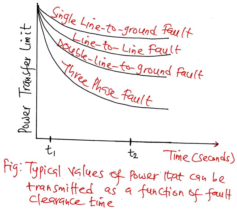
From the graph, it is easy to see that a fast clearing time of t1 allows a higher power transfer than t2 which affords a longer clearing time. Currently, the fault clearing times on bulk power systems lies within the t1 region which is about three cycles on a 60Hz base with the effect that power transfers are almost at a maximum.
The most severe faults are the three-phase fault with the least being the single-line-to-ground fault regarding the transmission of power.
Simplicity: This involves excellent design from the perspective of minimum equipment and circuitry. It is worthy to keep in mind that the most straightforward protective system may not always be the most economical one even though it may be the most reliable from the standpoint of fewer elements that are likely to fail.
Stability: Stability is the property of the protective device that allows it not to operate with faults occurring outside the protected zone which is often regarded as external faults.
Economics: The target here is to achieve top-notch protection possible at the least cost. It is possible to achieve a protective system design that is very reliable but at the expense of high cost. Therefore, high reliability should not be pursued exclusively without monitoring the cost implication. There must be a way to strike a balance between economy and all the favourable characteristics mentioned above while considering all factors.
Zones of Protection
Protection involves all actions that continuously monitors the power system with the aim of detecting the presence of a fault and initiating the correct tripping of a circuit breaker. The circuit breakers do not work in isolation but must work in tandem with the relays. The relays are there to detect the existence and location of the fault, and in the event, there exists a fault, the relay will determine the circuit breaker to clear the fault rightly.
Therefore, a protective system is made up of several auxiliaries which include; Current Transformers (CTs), Potential Transformers (PTs) and Protective Relays with their associated wiring (which is known as the ac part of the system. The relay contacts also can close a circuit from the station battery to the circuit breakers trip coil (known as the dc part of the system and is supplied from the station’s batteries).
In general, all protective relays have two positions: the normal position, usually with their contact circuit open and (2) the fault position, generally with their contact circuit closed.
A relay has to have the right sensitivity for it to operate under minimum fault conditions for a fault within its zone while remaining inoperative under maximum loads or through fault conditions. This condition means that the relay should be able to know the difference between a fault current and an overload current.
Let us take for example that a transformer is afforded protection; the relay should not operate for the inrush current (inrush of magnetising current) which is momentary but may be of a magnitude of say, five to seven times the full load current.
Likewise, when we offer protection for a transmission line, the relay should not operate during switching of the transmission line or transient overvoltage caused by lightning. Similarly, the relay should be able to ignore the possible power swings that may take place in interconnected systems.
Protection Zone
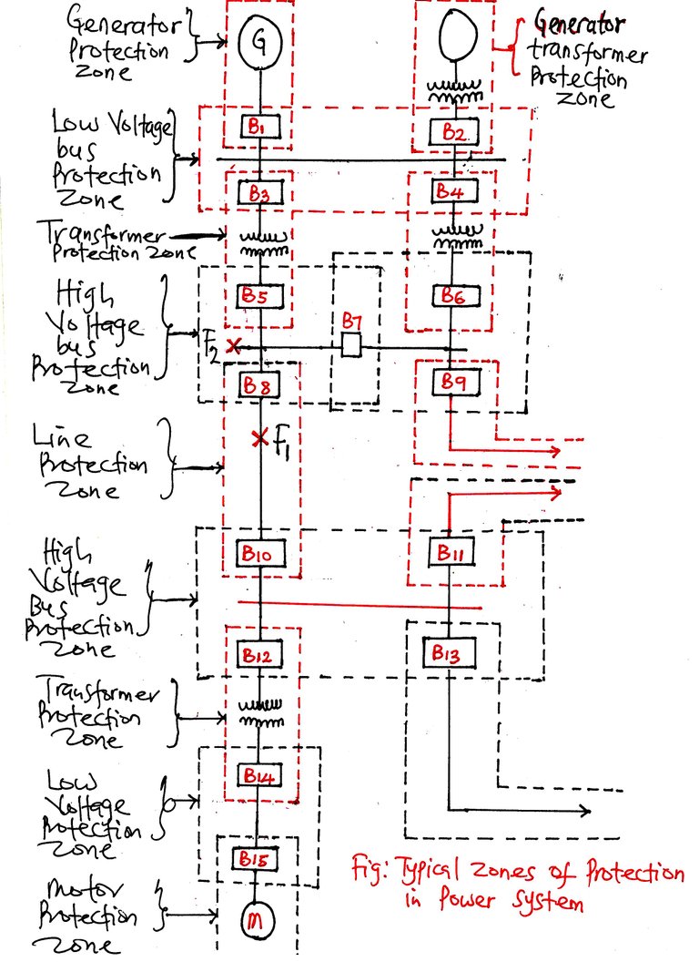
From the schematic above, we can divide the power system into protection zones to be able to provide adequate protection with minimum interruption. The protection zone is divided into:
- Generators (or generator-transformer)
- Transformers
- Buses
- Transmission Lines
- Motors
Each protective zone has dedicated protective relays for detecting the existence of a fault in that zone and its circuit breakers for disconnecting their area from the rest of the system.
We can define the protected zone as a segment of a power system protected by a given protective system or a portion of that protective system. In a well-designed primary protective system, any failure occurring within a given zone should cause the tripping (i.e. opening) of all circuit breakers within that zone and only those breakers.
Therefore, the primary protection is the protective system that is usually expected to operate in response to a fault in the protected zone.
As shown in the diagram above, each zone is overlapped to prevent the possibility of unprotected (or blind ) areas.
If a fault occurs at fault point F2, circuit breakers B5, B7 and B8 should be opened. For the possible event of the primary protection, e.g., due to malfunctioning of a primary relay or a circuit breaker failure to open when needed, backup protection must be provided to remove the faulty part from the system.
Backup protection is the protective system that is intended to supplement the primary protection in the event the primary protection should be ineffective or fails to cater for the faults in those parts of the power system that is not readily included in the operating zones of the primary protection.
The primary back-up relaying can be located can be located on another element of the power system, which can be the neighbouring station. This is to reduce the possibility of simultaneous failure of both the primary and backup relaying. We describe such arrangement as remote backup relaying.
The remote backup is slow and usually disconnect a greater portion of the power system much more than is necessary to isolate the faulty part of the system.For example, if circuit breaker B8 should fail to open for a fault at the fault point F2 , circuit breaker B10 should be opened instead.
It is crucial to delay the opening of the backup protection to give the proper breakers a chance to operate first. The reason being that the primary protection will just isolate the immediate area of the fault while he back-up protection will take down a bigger portion of the power system
Conclusion
In general, backup protection, we provide the backup protection bearing in mind that there is a possibility of failure of the primary relaying system and circuit breakers. There it becomes imperative that any backup protection has the duty of providing both the relay back-up in conjunction with circuit breaker back-up.
In totality, there are three kinds of backup relays, those that trip the same circuit breaker if the main relays fails (relay back-up); those that open the next nearest circuit breakers on the same bus, if one of the local breakers fails to operate (circuit breaker back-up); and those that operate from the next station in the direction facing the source in order to give a backup both the relays and circuit breaker (back-up) protection.
For the relay to coordinate the above functions and know when to operate the back-up, it must have an inbuilt delay time, and as such we can describe the coordination time delay as the delay time that is necessary to coordinate the primary and the backup protection. The coordination of protective relays especially for the interconnected systems is a bit complex, and as a result, they are done by using several computer programs.
Being A SteemStem Member
One or more of your photos is breaking some form of copyright or it is not sourced, whether it be that the photos require proper attribution or are licensed in such a way that they are not free to use. For more information, check out this post here on steemstem copyright standards.
Sincerely,
@kryzsec
Thanks for the Observation, I have corrected it @kryzsec . It is rightly sourced now. Many thanks.