I'm finally making progress on the T26E5 model, and as of this post, I've just finished [what I hope will be] the most frustrating part of the design: the running gear.
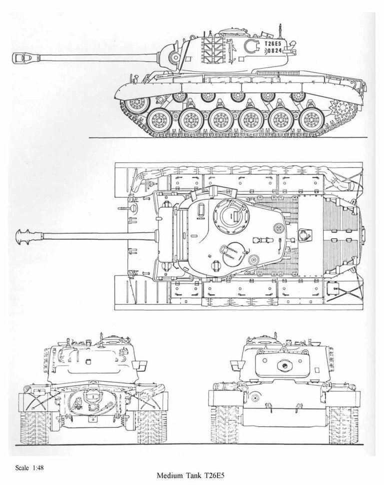

I need a break from this. I thought, going into this, that it would be just like the T29, since the T29 is basically just a stretched-out version of the T26. However, since I have a better drawing for the T26E5 than I did for the T29, that means I can make this one much more detailled.
Now, before I show you what I did, I must share some complaints I have with the design of American tanks. First, the hulls tend to have much more complicated geometry than contemporary Soviet tanks. Second, during World War II, American tanks tended to have double-bogie running gear with either a horizontal volute spring suspension (HVSS) or vertical volute spring suspension (VVSS), whereas torsion bar suspensions, such as that on the T26 and T29, were rare. The justification that I heard for this was that "bogie suspensions were simpler and easier to repair in the field." Having already rendered lots of Soviet tanks, I saw this argument as total nonsense. Apart from the T-34 and T-35, all Soviet tanks from World War II had torsion bar suspension, specifically because they were simple. The T-34 had a Christie suspension, but its successor, the T-44, had a torsion bar suspension. Rendering the T29, which had a torsion bar suspension, and the Sherman Firefly, which has a VVSS suspension, served to only reinforce my position. However, while I still maintain that torsion bar suspension are simpler than double-bogie suspensions, the suspension on the T26 is anything but simple. So far, I'd say that the Sherman was easier to render than this thing.
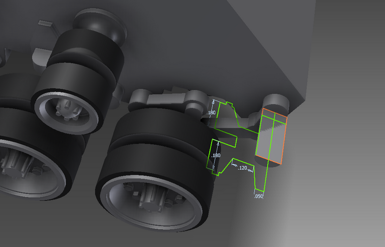
To begin, there is this ridiculous linkage connecting the first road wheel to the front idler:
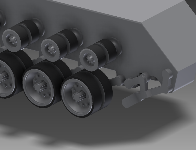
This means that, when the front road wheel is forced up from a bump in the road, then the front idler pivots and is forced forward, increasing the track tension. WHY?! That's just the beginning of this convoluted design, by the way.
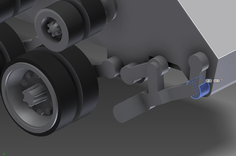
I highlighted the axle about which the link mounting both wheels rotates:
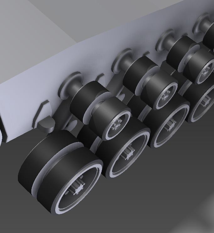
Once this was all drawn up, I created a rectangular pattern of the road wheel and its bolts:
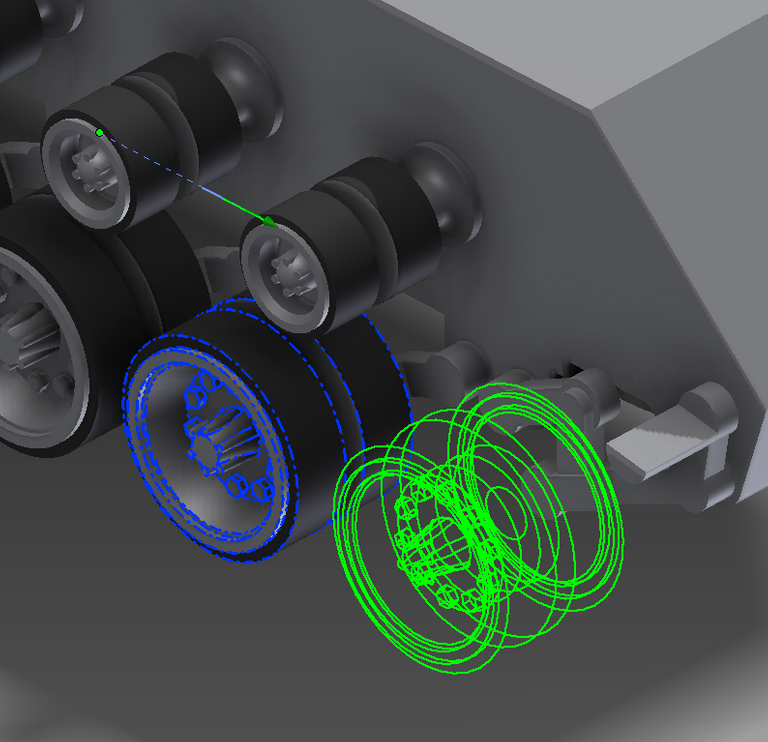
After that, I just copied the sketch for the road wheel onto the axle for the front idler:
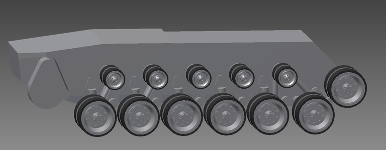
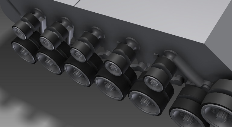
Hard part, easy part, hard part - that's how this is going. Well, the next step was to add the shock absorbers, but Inventor collapsed from exhaustion and crashed - which it has a tendency to do when I've been rendering complicated models for a while. It's not that adding the shock absorbers was particularly difficult, only that I had to do it twice. The two shock absorbers mounted in the back are both mounted the same way, but the two in the front are not, as you can see from both the drawing and the photo of the incomplete model kit. Here are some screenshots of the shock absorbers in place:
Admittedly, I got a bit lazy with that part, but even on a 1/100 scale model, those details are not going to be easy to discern, and I sell mostly 1/285 scale models, so most of these details won't show up anyway. At least this model is worthy of being printed in 1/100 scale (or will be, when it's finally done), unlike my T29 model.
Once this is done, I'm going back to sailing ships for a while. I have a French carrack, Venetian galleass, and Ottoman galley to make.
Shameless self-promotion:
Shapeways:
https://www.shapeways.com/designer/steampunkkaja
WordPress:
https://kjworldsong.wordpress.com/
Wargaming 3D:
https://www.wargaming3d.com/vendor/kajminiatures/
BitChute:
https://www.bitchute.com/channel/hyLVDAKeGZC9/
SubscribeStar:
https://www.subscribestar.com/kaja-blackwing