Let’s start with some basics, so what is clutch ?
Clutch is a mechanical device which simply used to engage or disengage the power transmission from engine to the gearbox.
While stopping the car or changing gears when we push the clutch pedal then the clutch plate disengages the driving shaft which is coming from engine to driven shaft which goes to gearbox because engine is constantly running at the time of changing gear or stopping the car so we have to disengage the engine so to change gears smoothly without any wear on the gear teeth.
I have designed this roll cage on SolidWorks-2016 because it has good user interface and smooth working with high quality graphics. So let’s start....
.png)
Our designing, it’s not just a single part it’s a whole assembly so I have made each small parts differently then assemble them to make a clutch plate assembly.
Parts made for the clutch plate assembly are: BALL BEARING, NUT, BOLT, BRACKET, CIRCLIP, CLUTCH PLATE, DRIVEN FLANGE, DRIVEN SHAFT (for better assist in designing), DRIVING FLANGE, DRIVING SHAFT (for better assist in designing), FRICTION DISK, OIL THROW RING, SPRING, PIN FOR SPRING, PIN, RIVET, SEATING FOR SPRING, SLEEVE SLIDING, SUPPORT PLATE and TOGGLE LEVER.
ALL THE CALCULATIONS ARE DONE BEFORE DESIGNING.
BALL BEARING:
.png)
.png)
Here ball bearing is used to reduce the friction, give a support to shaft and absorb jerk, As you can see in above picture I have made two figure basically 2D drawings it’s the cut through section of the two rings of the bearing then using REVOLVE command I have revolved keeping the line of reference at the distance of radius of the bearing, now we get a 3D cylindrical shape.
.png)
.png)
Now for I have made a semicircle as you can see in above picture then revolving around its diameter using REVOLVE command we got a sphere (a ball) then using CIRCULAR PATTERN command I have made the desired number of balls there is two lines of ball in my bearing for better support to the shaft, our ball bearing is ready to roll..!!!
NUT:
.png)
.png)
For making nut first i have made a hexagonal 2D drawing then using EXTRUDE command I have made a 3D extruded nut body then using FILLET command i have curved the edges then using EXTRUDED CUT command i have made a circular hole throughout its cross section.
.png)
.png)
Then selecting the reference as the circumference of the circular cut using HELIX command I have made a spiral which acts as a reference path for the circle thus using CUT-SWEEP command I have made spiral cut which is called thread in technical terms in the inside curved surface of the circular cut as you can see in above picture thus our nut is ready.
BOLT:
.png)
Same procedure is followed as in nut, first made a 2D hexagon then extrude it then made a 2D circle on a face of it then extrude it using EXTRUDE command, thus we got a nut shape and using similar steps as in nut I have made spiral using HELIX command which is used as a path for circle then using CUT-SWEEP as shown in nut I have made the thread in the bolt and our bolt is ready.
BRACKET:
.png)
Bracket is use to support the toggle lever, as you can see in first picture the above potion is made by REVOLVE command revolving a rectangle 180 degree along one of its larger side then we get a semi cylinder then making a rectangle and extruding I got the middle portion the then on its lower side I have made a 2D drawing according to design and extrude it to get the lower portion.
.png)
Now in above second picture using EXTRUDE CUT command I have made holes on the base to screw it into the driven flange and made a cut on the above portion so toggle lever can fit, holes are made to screw up the toggle lever, thus our bracket is ready.
CIRCLIP:
.png)
.png)
As you can see in above picture I have made two 2D drawings then using SWEEP command swept the circle across the path thus we get a 3D circlip.
CLUTCH PLATE:
.png)
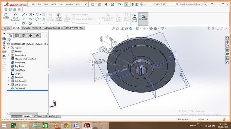.png)
For making clutch pate I have made a 2D drawing then revolve it using REVOLVE command, thus we get the basic structure, then using EXTRUDE CUT command I have made a few hole which goes throughout the plate in the center hole is for driven shaft and side holes is for bolts to clamp it.
DRIVEN FLANGE:
.png)
.png)
.png)
First made a simple 2D sketch then revolve it using REVOLVE command thus got simple 3D object then using EXTRUDE CUT command made some holes, centre hole is for driven shaft and others are for holding other parts and bolts, thus our driven flange is ready.
DRIVEN SHAFT:
.png)
I have made two cylinder using EXTRUDE command one over the other and a teeth is cut through CUT-SWEEP command, then using CIRCULAR PATTERN command I have made five teeth using the larger cylinder diameter as reference thus our driven shaft is ready.
DRIVING FLANGE:
.png)
.png)
First I have made a 2D drawing then using EXTRUDE command i have made one teeth and using EXTRUDE CUT command I have made holes through it using CIRCULAR PATTERN command I have made the pattern of the teeth at whole outer circular area, you see in the back there are small wholes which comes through it is used to transfer coolant oil so too keep it cool at high speed.
DRIVING SHAFT:
.png)
.png)
First I have made a 2D calculated drawing them using REVOLVE command I have revolved the 2D drawing and made a solid shaft and using EXTRUDE CUT command I have made holes to screw it on driving flange, you see some circular hole below it this is for roller bearing.
FRICTION DISK:
.png)
It is made up of hard material, first I have made a simple 2D drawing and using EXTRUDE command make it a 3D ring and then using EXTRUDE CUT command made holes in it.
OIL THROW RING:
.png)
First I have made a 2D calculated drawing then using REVOLVE command revolved it around an line which is placed far according to radius of the ring thus I got a 3D ring structure then using EXTRUDE CUT command made holes through it and our oil throw ring is ready.
SPRING:
.png)
As we discussed earlier the procedure of making threads in the bolt the same procedure applied here a helix is made and used as a path to follow for a circle using SWEEP command we got a 3D spring.
PIN FOR SPRING:
.png)
For making pin I have made a circle and extrude it and another circle on it then by the thread making procedure described above I have made thread on both sides of the pin and made a hole at the lower end throughout for the circlip.
PIN and RIVET:
.png)
.png)
It’s just made by revolving a simple 2D drawing using REVOLVE command, a hole is made at the lower end of the pin for circlip.
SEATING FOR SPRING:
.png)
It gives a base support to spring it acts as a casing, I have made a 2D drawing then revolving it using REVOLVE command.
SLEEVE SLIDING:
.png)
.png)
First I have made a 2D calculated drawing then revolve it using REVOLVE command using a base line as per driven shaft radius then revolving it we have our sleeve sliding.
SUPPORT PLATE:
.png)
Support plate is placed after the clutch plate it gives an extra to absorb jerk and tightly engaged while driving, I have made a 2D drawing and extrude just simple and thus made our support plate.
TOGGLE LEVER:
.png)
.png)
.png)
Toggle lever is mounted on driven flange and gives support to sleeve sliding, I have made a simple calculated 2D drawing then extrude it using EXTRUDE command and then drawn two circle at both ends and extrude it as shown in above pictures then using EXTRUDE CUT command I have trimmed the lower portion and made a hole in the bigger cylinder to pin it on the driven flange.
FINALLY ALL PARTS ARE MADE, AND THEN IT’S TIME FOR ASSEMBLY.
I have used coincident, distance, path, and circumference mates to assemble all the parts, but this post is going too long so I put a fast 10sec assembly video.
vimeo.com/244736822
So now after assembly our final master piece a custom clutch plate assembly is ready.
.png)
.png)
.png)
PLEASE GIVE YOUR SUGGESTIONS AND REVIEWS FOR MY HARD WORK AND IF YOU LIKE IT PLEASE DO UP-VOTE AND FOLLOW. If you have any suggestions or queries can tell me in comment and I will write my next blog on it.
THANK YOU FOR READING.
wow! Ur good at this!!! And your post is always of quality!
@originalworks
The @OriginalWorks bot has determined this post by @afzal-anees to be original material and upvoted(1.5%) it!
To call @OriginalWorks, simply reply to any post with @originalworks or !originalworks in your message!
very informative article, briefly described really liked it
keep it up
This if he is one good post
I'm no good with mechanical parts, but this post obviously shows your hard work. Upvoted and trying to digest (understand) all these.
Thanks my friend I really worked hard and tried to show every simple steps and the reason behind it so people from non technical fields can also understand it.