I want to show you my first powerbank I have build, explain how it works and a little bit how I have build it.
It uses eigth 18650 lithium-Ion batteries each messured and tested around 2600mAh.
I tested each cell with the opus bt-c3100:
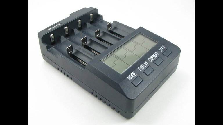
Therefore the powerbank has around 21000 mAh which is quite good.
Materials I have used (example links):
- 8x Samsung ICR18650-26F (I got them from an old Laptop Battery)
- Tp4056 protection board
- StepUp boost converter like these | Also possible
- resistors 2x200 ohm and 10kohm
- Micro USB Breakout Board
- Usb Type A
- RGB LED
- 2x Red LED (you could also use one RBG Led)
- momentary switch
- toggle switch
- 5A fuses
- Casing
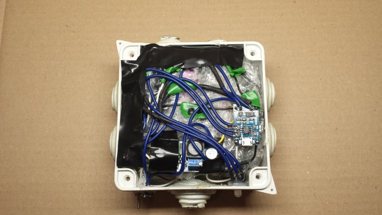
Wiring in my Powerbank (really messy not recommended):
I also made a easy circuit diagram for better explanation:
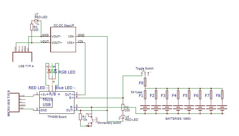
If you want to build your own powerbank connect everything as shown in the circuit diagram.
Explanation:
The TP4056 lithium-ion battery protection board uses, like the name suggest a TP4056. Also it uses a DW01x and a ML8205A.
The TP4056 is a lithium-Ion battery charger IC. The Dw01x is a lithium-Ion battery protection IC. It checks for over discharge, over charge and over current. Simplified it checks if the Battery is full or empty and is to quickly discharged. If it detects one of these contidions it turns the ML8205A off. The ML8205A is a dual N-Chanel mosfet. It works simplified like a switch. If turned off it disconects the Battery from the Protection board and load.
The momentary switch is used, because the Toggle switch disconects the battery cells completly from the protection board. Therefore when the toggle switch is turned back on the mosfet can't turn on because the Protection IC has no power to control it. The Toggle switch is bridging the mosfet. Therefore the protection IC can get power and turn the mosfet on. Dont use a Toggle switch instead of the momentary switch! This would result in permanant bridging over the mosfet. Therefore it disables the protection as long as the toggle switch is turned on.
The StepUp converter steps the voltage from the battery cells ranging from around 3V-4.2V up to 5V.
The RGB LED indicates if the Battery is charging and fully charged. The Two Red LEDs are indicating if the toggle switch is turned on (Led U4) and the other one (Led U7) if the output is on.
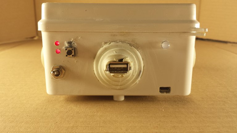
Some pictures from the powerbank:


Hopefully you could understand my circuit diagram and explanation and maybe learned something.
If you have any questions I will try to answer them.
If you want to build your own please be careful and only do it if you know what you are doing. Batteries especially Lithium-Ion and Lithium-Polymer Batteries can be dangerous if not handled properly.
Have a nice day!
How long does it take to charge the whole pack with the single TP4056?
What software did you use to generate the electrical diagram?
Are you going to use solar for charging all of those packs?
Thanks for your questions.