Hello Steemians,
today I want to show you how the so-called "Tesla Transformer" works. There are many ways to built a tesla transformer, today we want to discuss the easiest circuit for this purpose, which is the so-called “slayer exciter circuit”.
But first you need to know how a tesla transformer simplified works. A normal transformer changes an AC-voltage to a different voltage level. There are many purposes for this function: safety, power distribution, high current transformers (for welding) and so on.
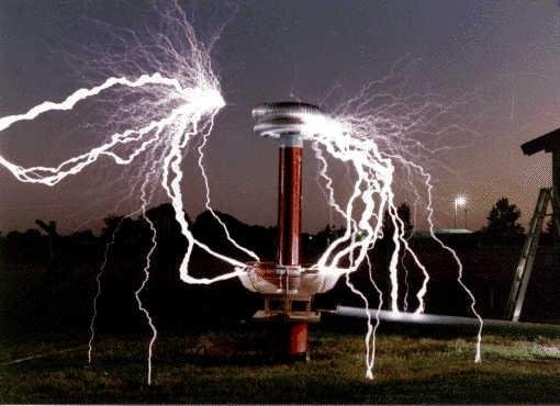
A tesla transformer also changes an AC-voltage do a different voltage level, but with a hugh translation ratio and really bad efficiency. So it shouldn’t be used for powering devices or similiar, it’s mostly just for fun. With it you can create output voltages in the order of multiple hundred thousand volts, with a low and mostly safe input voltage, and with that you can create beautiful arcs or you can power some devices like fluorescent lamps, because of the high electric field around the secondary winding (still really bad efficiency).
But how can the translation ratio be so big?
The translation ratio of a normal transformer depends on the number of windings on the primary and secondary coil. The formula looks like this: U2 = U1 * (W2/W1), so the bigger the difference in windings, the bigger (or smaller) is the translation ratio.
A tesla transformer needs to operate at the resonance frequency of its tank circuit (L2 and C) on the secondary side to boost the secondary voltage further. If a tank circuit operates at its resonance frequency the main components L and C will be putting charges into each other and therefore boost the voltage, this process is only limited by the electrical resistances. You can imagine it like a swinging pendulum and everytime the pendulum swings to an end you give it another push, so its amplitude will grow strongly. The same thing happens between the secondary inductor and the parasitical capacitor in the air. So the frequency of the AC-Voltage must be tuned to the resonance frequency of the circuit to create such boosts. You can calculate the resonance frequency with that formula: f = 1/(2 * pi * root(L2 * C))
Below you find the slayer exciter circuit, where R is a resistor(to limit current), D is a Diode, C is the parasitical capacitor betweent the top load and earth, L1 is the primary and L2 the secondary winding and T is a bipolar transistor. As you can see we don’t need much components, so its cheap to build. The bad side is that this circuit is really inefficient compared to other solid state tesla circuits, but therefore it cant really hurt you ;)

How does it work?
As we know a transformer only works with AC-voltage and now we powering our circuit with a DC-Voltage, how can that work? We simply create our own crude AC-voltage with a changeable frequency by chopping the DC-Voltage with the transistor. The nice thing about this circuit is that it will tune itself automatic to the resonance frequency, so we don’t need to calculate and tune the circuit ourselfs.
The transistor works in this circuit basically as a switch, if we turn on our DC power source a base-emitter-current starts flowing and the transistor will reduce the resistance between collector and emitter and therefore become conductive (switch closed). A rising current will start flowing through the primary winding and create a magnetic field, which induces a rising voltage on the secondary. The air capacitor on top of L2 will resist the voltage change, which leads to a rising negative voltage and the bottom of L2.
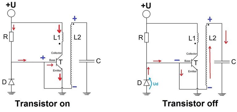
If the negative voltage on the bottom of L2 is higher than the forward voltage of the diode D current will flow through it and through the secondary winding and the capacitor. If this happens the base-emitter current will stop flowing, because we now have a negative voltage on the base and therefore the transistor will become insulating between collector and emitter (switch open). This stops the current flow through L1 and therefore stops the voltage induction in L2. The magnetic field in L2 starts reducing. After that the process will start over and so the output voltage boosts itself higher and higher.
Because of the tank circuit on the secondary we get a sinusoidal voltage in the order of multiple hundred kHz to multiple MHz (depends on the values of L2 and C).
Because of the feedback from the secondary winding, the circuit will tune itself exactly to that resonance frequency, where we get hugh voltages to ground at the top of the secondary coil, which will produce these beautiful arcs.
This simple principle can be further beeft up :)
First picture is from anonymous user "Antivolt", licensed under CC BY-SA 3.0.
Other pictures are proudly made by me with M$ Paint.
Congratulations! This post has been upvoted from the communal account, @minnowsupport, by Elektr1ker from the Minnow Support Project. It's a witness project run by aggroed, ausbitbank, teamsteem, theprophet0, someguy123, neoxian, followbtcnews, and netuoso. The goal is to help Steemit grow by supporting Minnows. Please find us at the Peace, Abundance, and Liberty Network (PALnet) Discord Channel. It's a completely public and open space to all members of the Steemit community who voluntarily choose to be there.
If you would like to delegate to the Minnow Support Project you can do so by clicking on the following links: 50SP, 100SP, 250SP, 500SP, 1000SP, 5000SP.
Be sure to leave at least 50SP undelegated on your account.