do it yourself!
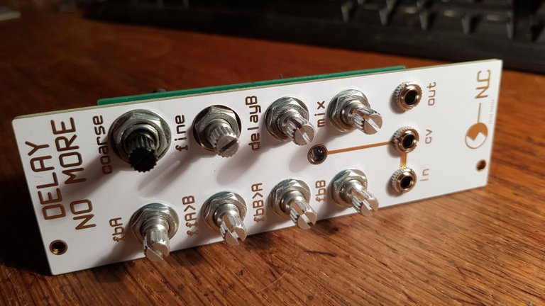
...this photo series starts right after installing all smt components, which isn't critical and not exciting to see. The rest is just a handful of through hole components but it's essential to do it in the right order if you like to have the best result. The module will be part of a modular synthesizer, eurorack format, design by Australian synth designer nonlinearcircuits, one of my favorites.
It is based on the PT2399 delay chip, and this module is in fact designed to be a chaotic noise module, not really a normal delay. After first tests I have to admit it is even weirder than the slightly different one from the large cellF action panel, it's here to stay.
This blog post here is meant to be a description for a friend who's just starting out in synth diy (sdiy) to get it running on first try without magic smoke, and I think it could be interesting for others too.
Alright, here we go:
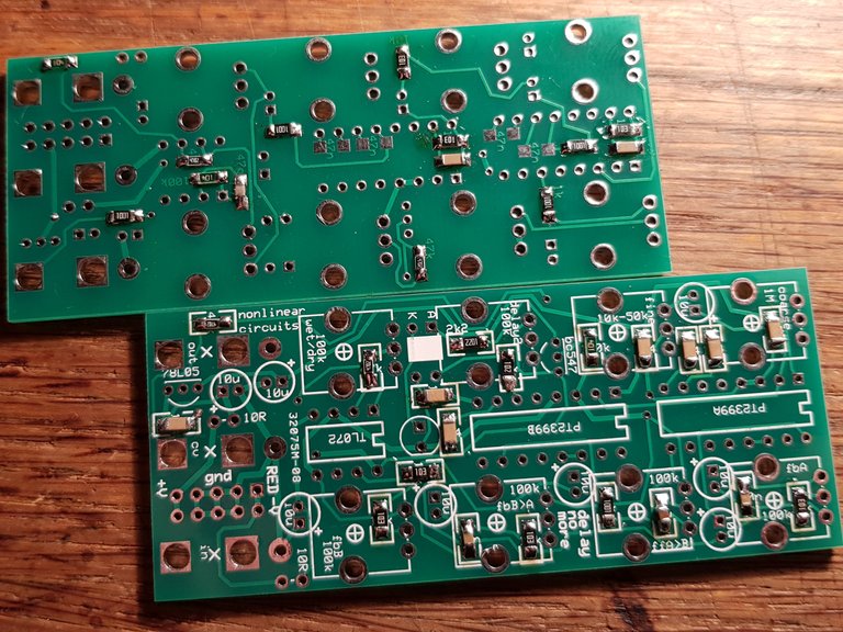
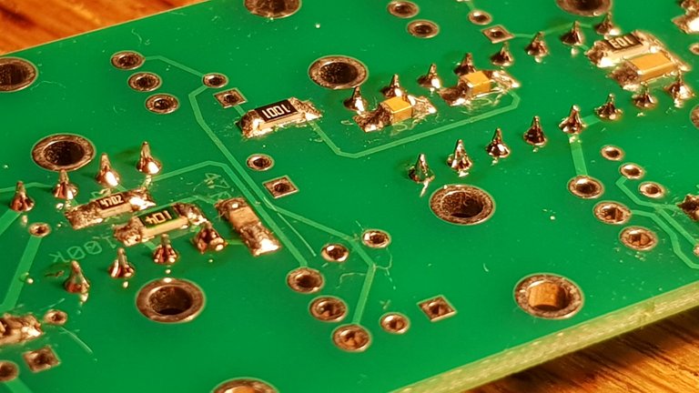
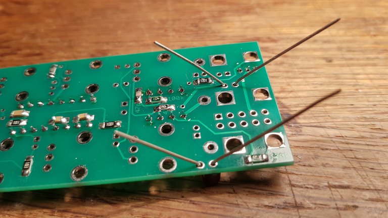
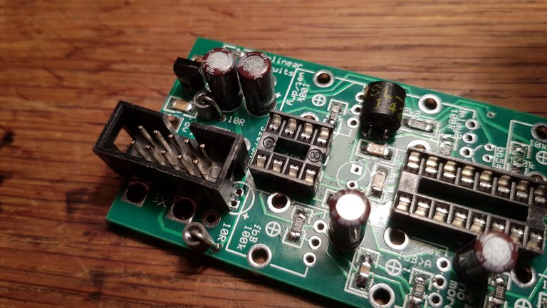
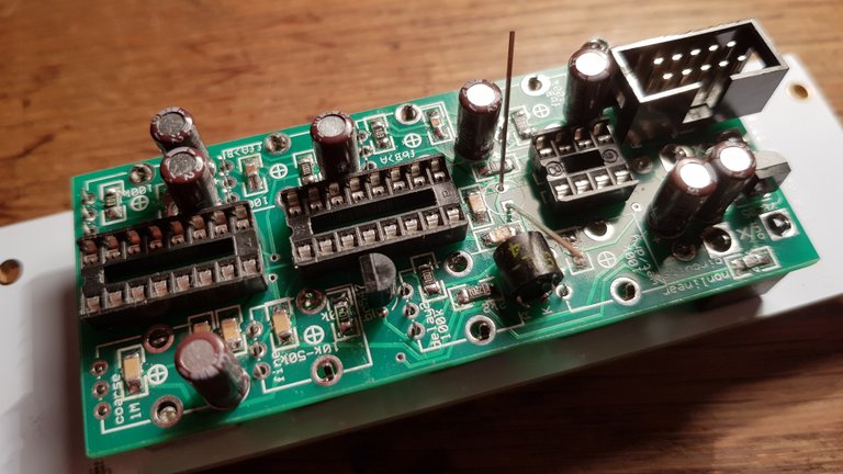
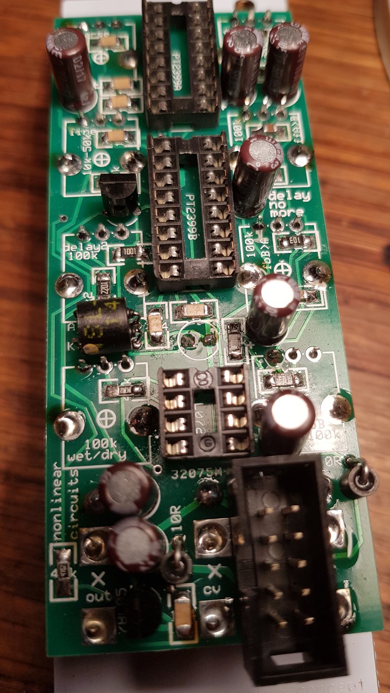
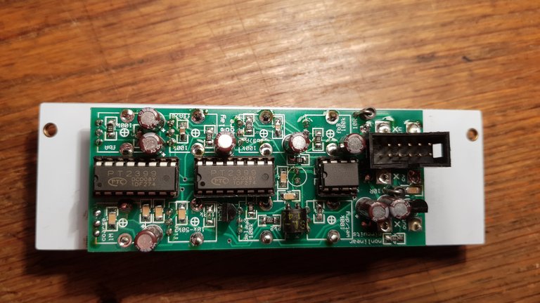
This picture shows the boards with the smt parts already installed (some capacitors on the bottom side still missing), ready to start the through hole work.
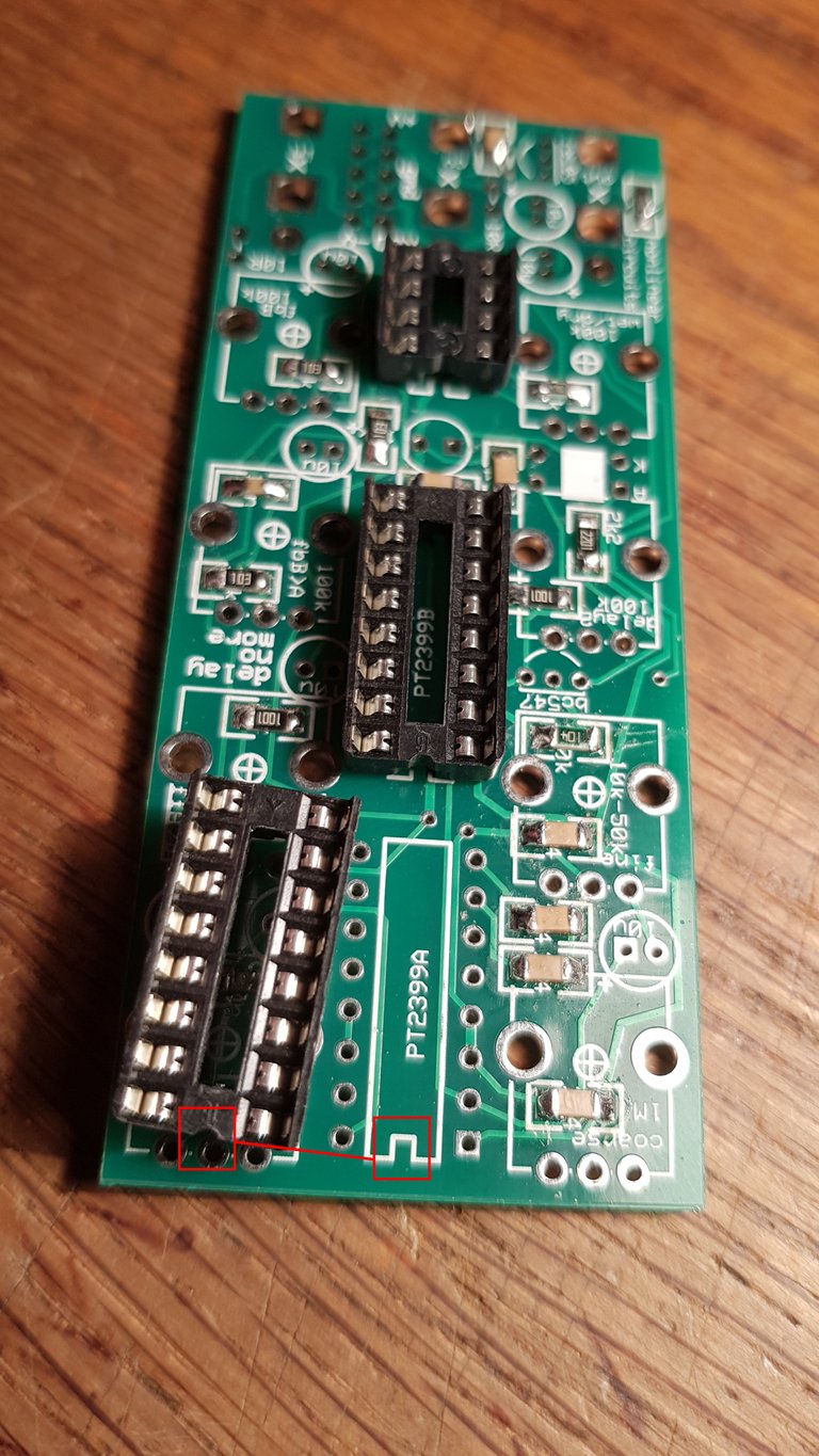
First the IC sockets. Pay attention to the correct alignment. The notch on the socket must be in the same place as the notch on the label on the circuit board. The chips have the same notch.
When positioned correctly hold the sockets in place while turning the board upside down, to solder.
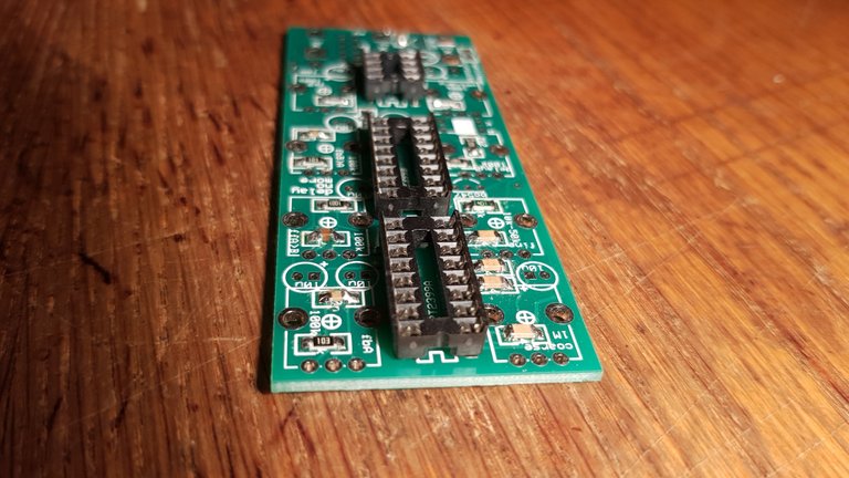
I start by soldering two opposite corner pins of each socket. Then I take it in the hand and press the socket on the pcb while reheating both corner solder joints, to make it straight and flat on the surface. After that I solder all the other socket pins. Reheat until all solder joints look ok.
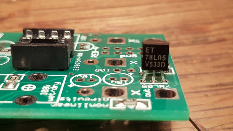
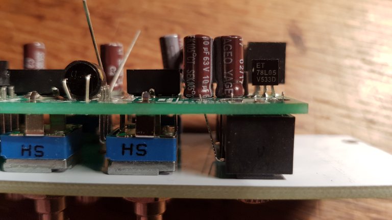
Then I installed the voltage regulator. Case has to be aligned with the label on the pcb. I usually bend the outer legs away and solder the middle leg first. Make it stand straight while reheating, then finish soldering the outer legs. That way it also doesn't overheat.
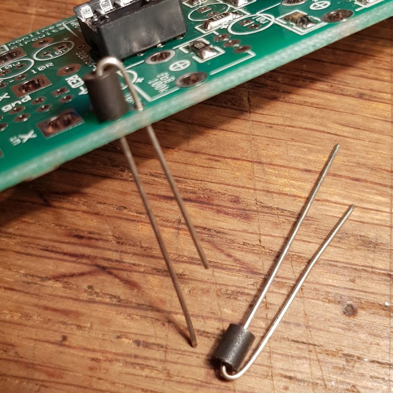
Now the two ferrite beads . I use them in place of the 10R (10 Ohm) resistors. The resistors are supposed to function as a kind of fuse, but since we're not planning to make any mistakes we can use ferrites, they have even less resistance and filter out some high frequency noise from the power rails.
Solder the longer leg first, that's the component body standing upright. You can move it on the other side while heating up so it stands nice (careful, super hot). After soldering the second leg I would recommend heating up the first joint again to make sure there isn't a bad solder joint due to moving it while cooling down.
Next I installed the electrolytic capacitors, all 10uF. The left one in the foreground I had to remove again in order to install the power header. Better to wait with that cap until the end. Note there's a "+" sign at every label on the pcb. The side with the "-" stripe on the caps goes in the other hole, opposite to the hole marked "+". They are also marked with different solder pads. The + side is rectangular while the minus side is a round pad. So, again, don't install the one on the left close to the power header at this time. Turn the board around and solder only one leg of each capacitor while holding down the board, to make them all flat to the surface.
Hold them to the board with one finger while heating up the solder joint again shortly. Then lay it on the table and solder the other legs.

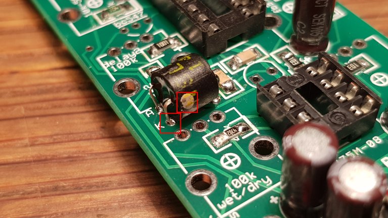
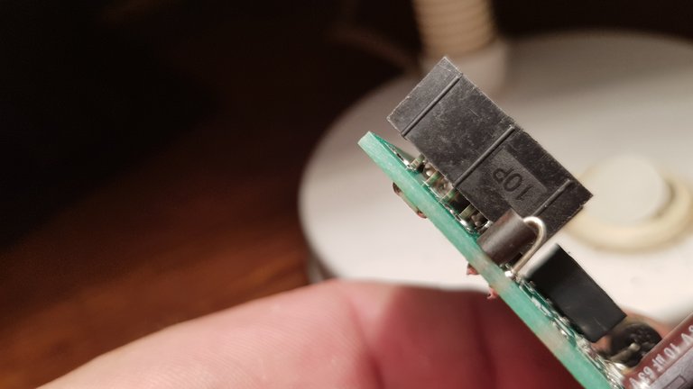
Now the optocoupler (Vactrol). The cathode is marked with a yellow dot on this one (Silonex 32) and goes to the hole marked K. The side with A and K are for the LED inside the Vactrol and need to have the right orientation (polarized), the other side is the LDR side of the opto isolator. Best practice is to bend the legs first, check orientation and then insert it (like in the second pic)
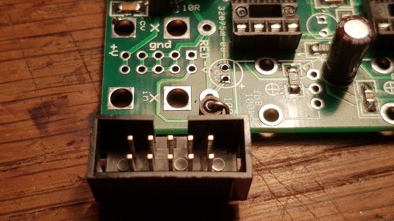
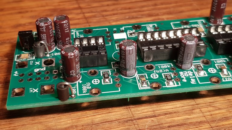
In this picture you can see the alignment of the power header in the Doepfer standard (Eurorack). When you look from the top and have the + side left and minus right, the key is away from you. That's the way the standard cable has to be connected. The red stripe would be on the minus side (right). By using this keyed (aka shrouded) header you can never put on the power cable the wrong way on this module, even in dark ambient studio atmosphere. The downside is that it's bigger than the normal headers and therefore we need to do 2 things to make it cool. (a) We need to install the aforementioned capacitor afterwards (the one with the longer legs in the kit) and (b) I install it a bit raised from the board in order to leave a little more space to solder the 3.5mm jacks that are directly below it.
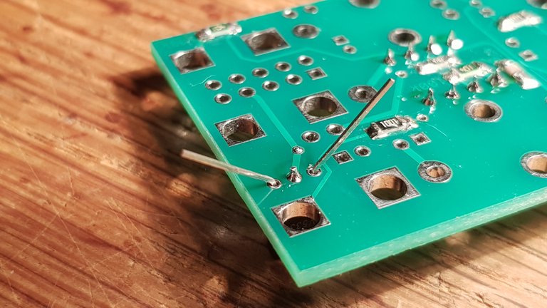
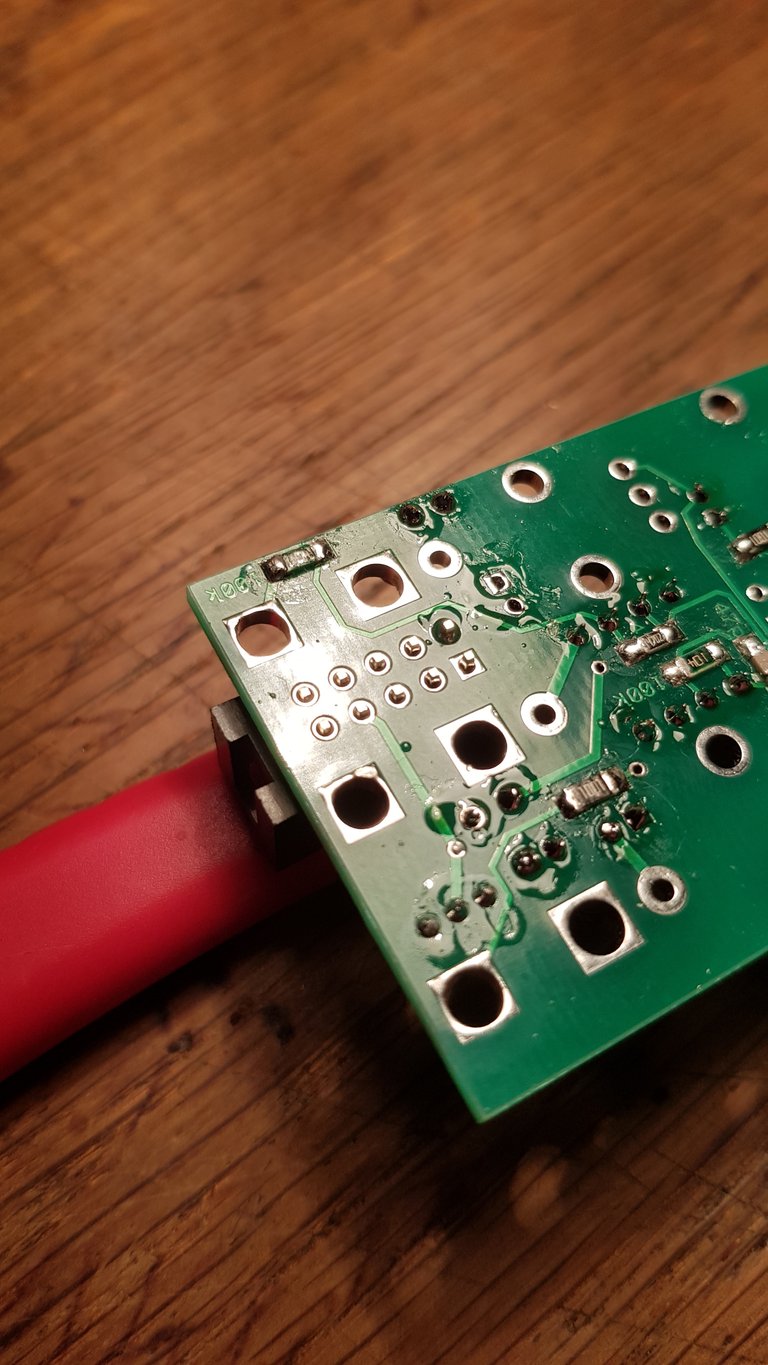
See how close the holes for the capacitor are now....
Only solder one corner. Then take it in your hand and adjust it to raise it from the board while heating up the pad.
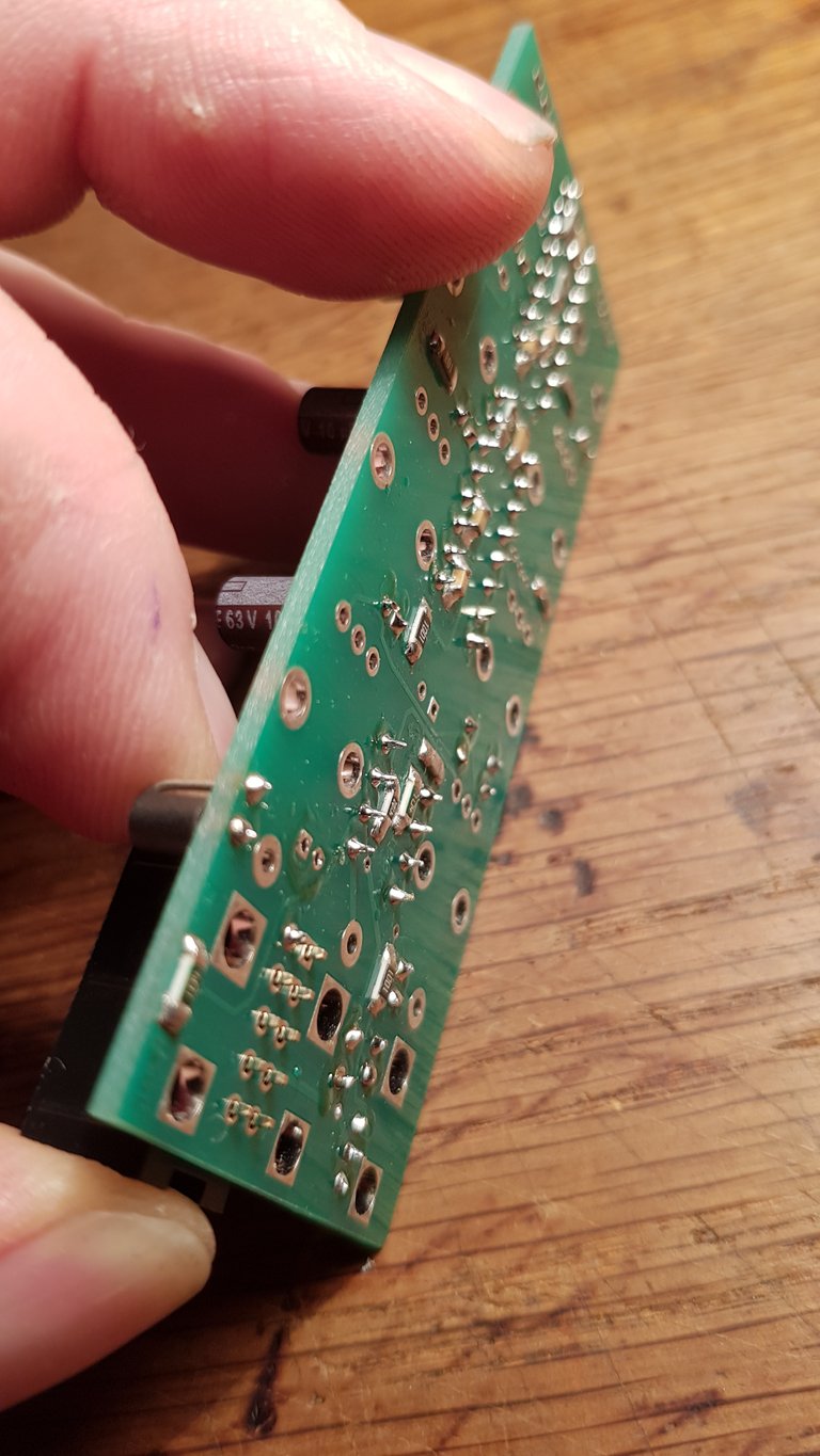
Repeat until the legs are all flush with the surface, that should be enough room to solder the jacks. Should be straight and look good too. Then solder all the legs and make sure you touch both the leg and the pad together so there is no cold solder joint. Both surfaces must be hot. Just repeat until it flows inside.


Now the capacitor with the longer legs:

Observe the orientation! (-) stripe on cap on opposite side of the (+) on the board!

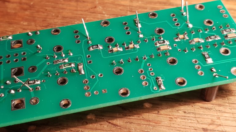
And I forgot to install the BC547 transistor (middle of the pic), align with the label on the board and do the same as with the 78L05 earlier. Right of the IC socket you also see the legs of the LED. This is after putting the board on the panel.
It's easy to do, just don't solder too early.
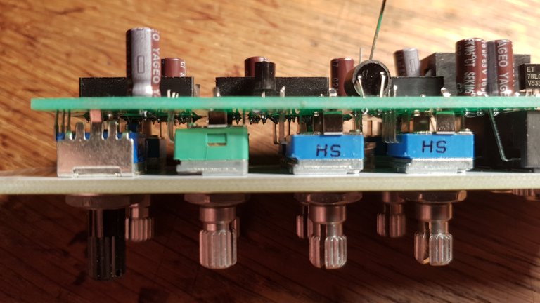
First you install the pots in the right places, don't solder anything yet. The bags are labeled with the function and the value. some have the metal pieces cut off in order to not touch copper traces or smt components underneath. Just put them in the holes. Then put the 3 jacks in the holes too. The same with the LED. It's a white high power led, mine works fine with it. On top of the board you see the label with one side flat, which corresponds with the case of the LED. You put the legs through from the other side, double check the alignment that the flat side is indeed where it is on the board (it's also the shorter leg, in the round hole).
Once you have it ready, put the front panel over the pot shafts and the jacks. You may have to start a few times until you got it all right. The LED comes later. Now install all the washers and nuts and fasten them by hand. The one pot in the upper right corner is not as tall as the others in my case. just fix it to the panel, the pins will just sit flush with the pcb on the other side. So when you have fixed the front panel components with the nuts it's time to start soldering them to the board. Check that the board is nice and parallel behind the panel. Then solder only one of the pins of each component, so that you can easily make adjustments if needed. Once that turns out well you can do the next pin on each component, check again and then solder them all. In the end put the LED through the panel as far as you like it (I have it so the rounded top just looks through the surface). Bend the legs, solder one, check again if it's alright, then solder the last leg.

You can see the difference between the 2 pots. That's ok. Just screw them all firmly to the panel and the board should be parallel automatically.

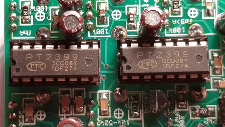
When everything is soldered I would recommend plugging it in (into the synth system) to see if everything stays as it should, no shorts, lights stay on etc. If all is ok, insert the chips in the sockets (observe orientation, the notch). Plug in again and touch the ICs to feel if they get hot. If not, screw it in and check out the crazy sounds!

Congratulations @antidorsessions! You received a personal award!
Click here to view your Board of Honor
Do not miss the last post from @steemitboard: