Hi, today I'm going to do a tutorial on How to Construct a Home-made Single Phase 220/24 V Step Down transformer. These tutorial was based on my personal knowledge, experience and ideas on How to Construct a Home-made Single Phase 220/24 V Step Down transformer,
let's start with the definition.
A transformer is a device used to change voltages and currents of AC electric power. In the simplest version it consists of two windings wrapped around a magnetic core; windings are not electrically connected, but they are coupled by the magnetic field, as it shown in the below.
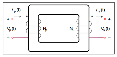
When one winding is connected to the AC electric power, the electric current is generated. This winding is called the primary winding. The primary current produces the magnetic field and the magnetic flux links the second winding, called the secondary winding. The AC flux through the secondary winding produces an AC voltage, so that if some impedance is connected to the terminals, an AC electric current is supplied.
Source: #https://en.wikipedia.org/wiki/Transformer*
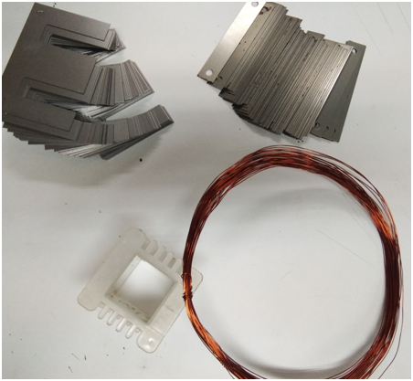
Materials Needed
• Magnetic copper wires (#25 & #20 AWG size)
• 1 pc. Core ( 1.25’’ x 1.25’’ )
• E-I Steel sheets
• Connecting wires
• Electrical Insulation Tape
Procedures
Calculate the necessary number of turns in the primary and secondary winding to come up with the desired voltage.
See attached photo below
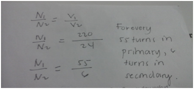
It implies that for us to have a step down transformer with 220/24 Volts. We are required to wind 56 turns on the primary winding for every 6 turns of secondary winding.Wind the core using #25 AWG size magnetic wires with the necessary number of turns. Do it uniformly to minimize copper losses. This serves as the primary winding.
See attached photo below
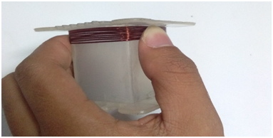
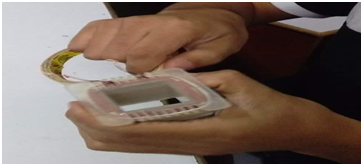
Cover the primary winding with a masking tape. This is done to isolate the primary winding to the secondary winding and to provide mechanical strength.
See attached photo below
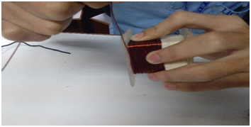
Wrap the primary winding using #20 AWG size magnetic wires the necessary number of turns in the direction opposite to the primary winding. This serves as the secondary winding.
See attached photo below
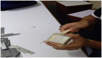
Then, cover the secondary winding with an electrical insulation tape to provide mechanical strength.
See attached photo below
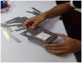
Place the E-I steel sheets alternately, making sure that all of those fits in the core. These laminated sheets gives the transformer the advantage of reduced flux leakage and iron losses.
See attached photo below
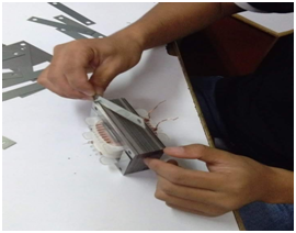
Lastly, connect a wire in the primary winding terminals for the input. Use a voltmeter to check the output at the secondary terminals.
See attached photo below
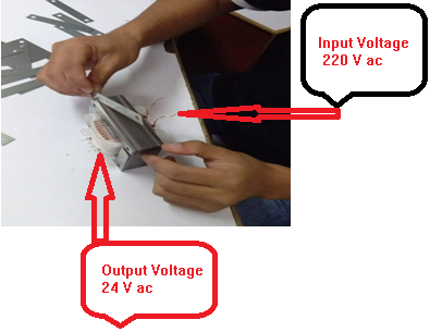
And the transformer now is ready to use.
Steem on Buddy
Wow this quite interesting tutorial @calmabryan27ree.... keep on steeming.. nice article.
Are those pictures yours?
the picture was taken during the experimentation in one of my classes. I really found it interesting and I believe that this picture may help others whom engineering enthusiast.thanks!☺
Cool, thanks for the reply :)
Wow i love it, hoe you like mine
@nikko2192
A very informative post for EE students, keep on steeming ☺
Being A SteemStem Member