What Will I Learn?
In this tutorial, readers:
- will learn advanced analyze techniques on the software
- will learn how to use "Data graph" on the software
- will be more familiar with logic circuit analysis
Requirements
In order to complete the tutorial, readers would have:
- Basic idea about logic designing
- Ability of reading a truth table
- a working PC, "Digital" software
Difficulty
- Intermediate
Tutorial Contents
In this tutorial, I am going to show some analyze techniques on the software which is called as "Digital". I will start my tutorial with the importance of analysis a digital circuit, then will move to Analysis function on the software, then will show the usage of Data Graph in the software.
Analysis and Data Graph functions will be shown via an example.(from a circuit that I have designed in one of my previous tutorial)
Lets start the tutorial
- Episode 1: What is analyze in digital circuits and why is it important?
Analyzing the digital circuit is the make connection between the theory and simulation results, which gives us an idea about the success rate of the simulation. By analyzing the circuit, actual behaviour of the circuit can be estimated easily and if it is necessary by the help of analyzing debugging can be done much more easier, since we know the source of the problem thanks to analyzing.
Analyzing in digital circuits can be done by the help of K-maps(which is not included in this tutorial), truth tables and by visualize the output with the corresponding inputs. In this tutorial, I will analyze a circuit by the thanks of the software "Digital". I am going to analyze the circuit that I have already constructed in my previous tutorial ( which reader can find it here)
Firstly, I will analyze the circuit by the help of Analyze function of the software, and then will show the output by the help of Data graph.
- Episode 2: Analyzing the circuit by the help of "Analyze" function on Digital
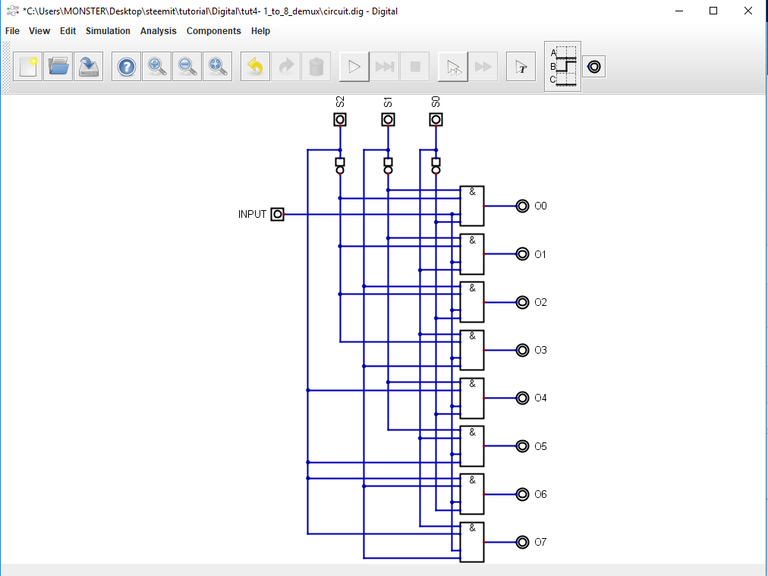
Let me remind the circuit that I have constructed before. The circuit schematic is given below:
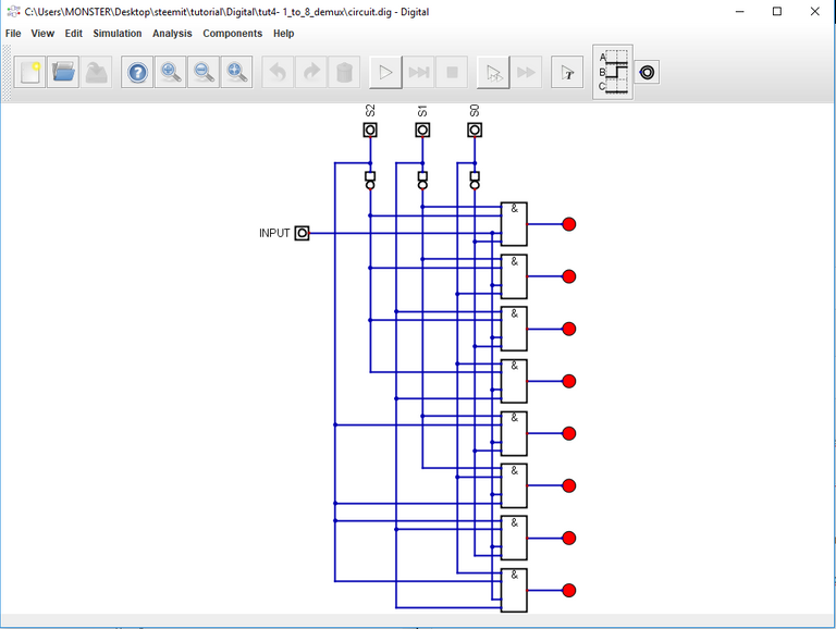
This is an example of "Demultiplexer" circuit. Now, in order to analyze the circuit, the first step is to LABEL each input and output. We have already named the inputs on the circuit, so we only need to LABEL each output with a different name(instead of connecting LEDs to them). To do this:
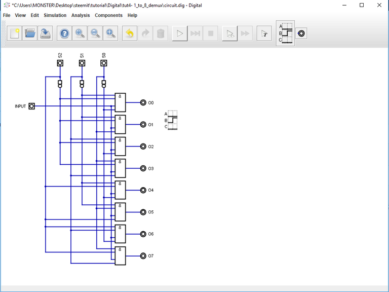
1- I will delete each LED

2- I will add 8-different output for each LED ( Components-->IO-->Out)
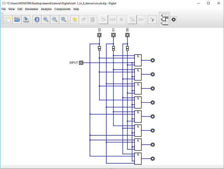
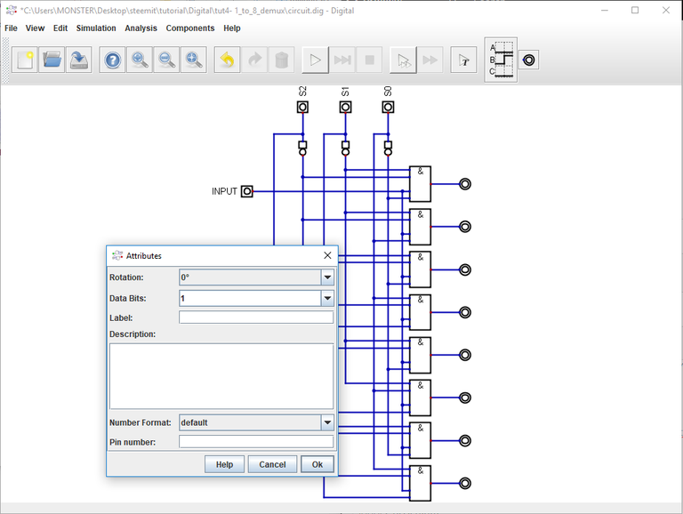
3- I will LABEL each output with a different name. ( To label outputs, we need to right click it and type desired label here)
Now we are ready to analyze our circuit.
In order to analyze, we need to click Analysis --> Analysis from the top bar, and the following screen will appear.

From here, we can see the expression for each output, and the corresponding truth table. I will also copy the truth table that I have prepared for this circuit (which is taken from my previous tutorial) here for comparison:
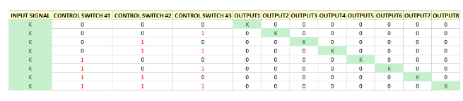
From here, we can easily see that, our circuits works perfectly.
- Episode 3: Analyzing the circuit by the help of "Data Graph" function on Digital
In this part, we will make analysis with the help of "Data Graph" on Digital. In this case we also need LABEL each input and output, I have done it above, so we can use same circuit to use Data Graph method.
In order to use Data Graph, we need to add a component from;
Components --> IO --> more --> Data Graph
After adding this component, and label each input/output with a different name; we are ready to analyze the circuit. The results are given below:
From here, we can read the graph, when any input or output is high it will go up in the corresponding lane, whereas low ones will stay bottom. Each combination of inputs can be visualize here to analyze / understand the circuit.
I have provided the files for this tutorial here. I highly recommend that the reader should work on the files that I have provided and try to understand the basics of the circuit & software. It will be benefical for he/she.
This is the end for this tutorial.Hope that you like it.
Digital is a really effective and easy to learn software, I highly recommend this software for the one who wants to make simulation in digital circuits especially. If you have any questions, please feel free to ask me on Discord (Escorn#4114)
Curriculum
I have provided the previous tutorials that I have prepared for the community:
| SimulIDE | Caneda | Digital | LogiJS |
|---|---|---|---|
| Part 1 | Part 1 | Part 1 | Part 1 |
| Part 2 | Part 2 | Part 2 | |
| Part 3 | Part 3 | Part 3 | |
| Part 4 | Part 4 | Part 4 | |
| - | Part 5 | Part 5 | |
| - | Part 6 | Part6 | |
| - | Part 7 | Part 7 |
Posted on Utopian.io - Rewarding Open Source Contributors
Thank you for the contribution. It has been approved.
You can contact us on Discord.
[utopian-moderator]
Hey @escorn I am @utopian-io. I have just upvoted you!
Achievements
Suggestions
Get Noticed!
Community-Driven Witness!
I am the first and only Steem Community-Driven Witness. Participate on Discord. Lets GROW TOGETHER!
Up-vote this comment to grow my power and help Open Source contributions like this one. Want to chat? Join me on Discord https://discord.gg/Pc8HG9x