What Will I Learn?
In this tutorial, readers:
- will learn basics of the K-map
- will learn usage of K-map method on Digital
- will be able to use K-map on the software
Requirements
In order to complete the tutorial, readers would have:
- Basic idea about logic designing
- a working PC
- "Digital" software
Difficulty
- Intermediate
Tutorial Contents
In this tutorial, we will cover K-map method on the software "Digital". On the list below, I will show the outline of the tutorial that we will cover:
1- Basic information about K-map method
2- K-map method on the software
3- An example design by using K-map method
4- Analysis & observation of the designed circuit
Episode 1: What is K-map method?
K-map (Karnaugh map) is a visual method to help the user to minimize Boolean logic expressions by giving a visualization,which users do not to use complex Boolean algebra and equations.
K-map method is very useful the circuits that has up to 6 inputs. Each combination of the inputs are visualized on the figure, and user can easily change and combine those input/output statements to obtain final circuit. Circuit implementation can be done easily by looking corresponding K-maps.
Following figure shows an example for 2-input K-map circuit.

When we have 2-inputs, we will expect 4 different output combinations. This figure summarized the case.
Episode 2: Usage of K-map on "Digital"
Our software digital has a K-map synthesise function inside it. That means that we can easily construct any combinational circuit by this function. To reach the function, we need to use the following path.
Analysis ---> Synthesise ---> KV-Map
Following screen is the expected screen when of K-map function on "Digital"

From here, we have 3 input , 1 output circuit. Name of the inputs: A,B,C , Name of the output : Y

First line corresponds the A NOT part of the circuit, and the second line corresponds to A part.(We can interpret B, and C with same way.)
When we clicked any combination on the table, the value changes by the following order.
0-->X-->1 ( Which means that if we click 0, it will be X)
User can have any combination of inputs on the table, an example of that combinations are shown below.

In that combination, corresponding expression is given in the black boxes. (X means that that combination can be both 0 or 1, that does not effect the output.)
By using that function, we can easily design any combinational circuits.
Episode 3: An example design by K-map
In this part of the tutorial, I will construct an example circuit. The statement of the circuit is the following.
4 input 2 output circuit. Output 1 is HIGH only when 2 of inputs are HIGH and Output 2 is HIGH when 3 of inputs are HIGH.
Construction of this circuit will be explained part-by-part.
- 1- Obtaining & Labeling 4-input/2-output
To obtain 4-input/2-output circuit, user need to click Columns part of the Synthesise function.

From here, addition and subtraction of any input/output can be made. When we have 4-input/2-output, corresponding function and K-map tables should look like :

User can label each input/output from the synthesise table.

Following figure shows the result when labeling is completed.

- 2- Configuring first output
To configure first output, we need to control the given statement above.
4 input 2 output circuit. Output 1 is HIGH only when 2 of inputs are HIGH and Output 2 is HIGH when 3 of inputs are HIGH.
From the statement, we need to adjust the table. ( We will 6 HIGH states which corresponds to following statements:
Only GATE 1 & 2 open, which is #12 on the K-map
Only GATE 1 & 3 open, which is #10 on the K-map
Only GATE 1 & 4 open, which is #9 on the K-map
Only GATE 2 & 3 open, which is #6 on the K-map
Only GATE 2 & 4 open, which is #5 on the K-map
Only GATE 3 & 4 open, which is #3 on the K-map)
Following figure shows the resultalt K-map.

- 3- Configuring second output
To move second output, we need to change the output from the table as shown below.

To configure second output, we need to control the given statement above.
4 input 2 output circuit. Output 1 is HIGH only when 2 of inputs are HIGH and Output 2 is HIGH when 3 of inputs are HIGH.
The configuration is explained on the first output case, so I will give the resultant table,which is:

- 4- Obtaining the circuit
To obtain the circuit, we need to click Create on Synthesise table.
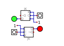
The resultant circuit is given below:

Episode 4: Observation of the circuit
The result of the simulation is given below:

From here, we can see that the circuit works perfectly.
I have provided the files for this tutorial here. I highly recommend that the reader should work on the files that I have provided and try to understand the basics of the circuit & software. It will be benefical for he/she.
This is the end for this tutorial.Hope that you like it.
Digital is a really effective and easy to learn software, I highly recommend this software for the one who wants to make simulation in digital circuits especially. If you have any questions, please feel free to ask me on Discord (Escorn#4114)
Curriculum
I have provided the previous tutorials that I have prepared for the community:
| SimulIDE | Caneda | Digital | LogiJS |
|---|---|---|---|
| Part 1 | Part 1 | Part 1 | Part 1 |
| Part 2 | Part 2 | Part 2 | |
| Part 3 | Part 3 | Part 3 | |
| Part 4 | Part 4 | Part 4 | |
| - | Part 5 | Part 5 | |
| - | Part 6 | Part6 | |
| - | Part 7 | Part 7 | |
| - | - | Part 8 | |
| - | - | Part 9 | |
| - | - | Part 10 |
Posted on Utopian.io - Rewarding Open Source Contributors
Your contribution cannot be approved because it does not follow the Utopian Rules.
You can contact us on Discord.
[utopian-moderator]
Congratulations @escorn! You have completed some achievement on Steemit and have been rewarded with new badge(s) :
Click on any badge to view your own Board of Honor on SteemitBoard.
For more information about SteemitBoard, click here
If you no longer want to receive notifications, reply to this comment with the word
STOP