What Will I Learn?
In this tutorial, readers:
- will learn the basics of 7-segment display
- will learn how to use a 7-segment display on "Digital"
- will be more familiar with logic circuits
Requirements
In order to complete the tutorial, readers would have:
- basic idea about logic designing
- basic idea about logic environment
- a working PC , "Digital" software
Difficulty
- Advanced
Tutorial Contents
In this tutorial, I am going to explain the basics of 7-segment display and usage methods of 7-segment display on the software "Digital". I will start my tutorial with explaining the basic operation principle of 7-segment display, and then will construct a complex circuit to make the concept clear on "Digital".
Before moving into explaining step, I want to say that the usage of 7-segment display on Digital is a bit complicated than the normal one, so I have recommend the reader that do not to try use this component before digest this tutorial.
Let me start with explaining the 7-segment display.
- Episode 1: What is 7-segment display?
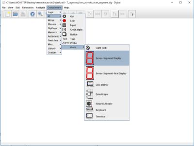
7-segment display is a digital component that have 8 inputs, and 8 outputs in the light form. This component is generally used to visualize the digital circuits to make more user-friendly and understandable. To reach the 7-segment display on the software, reader need to click:
Components --> IO --> more --> 7-segment display as in the following figure:
As I have said before, this component has 8 inputs, each one of them controls a LED, the order is important and I have prepared a figure to explain it. Numbered inputs controls numbered outputs as in the following figure:
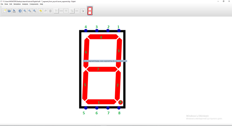
User should give high input (which is 5V on logic circuits) to open the LED, and give low input (which is 0V on logic circuits) to close the LED, and by controlling each input, user can visualize the logic circuit, which we are going to do in the next steps.
- Episode 2: Construction of a circuit to visualize 7-segment display
In this part of the tutorial, we will construct a circuit to understand 7-segment display better on "Digital". We will construct 3-bit asynchronous counter, then will use 7-segment display to visualize it. I have already explained the construction of 3-bit asynchronous counter in my previous tutorial, which is linked here, so this part will be short in terms of explanation.
Overall circuit construction will be explained step-by-step
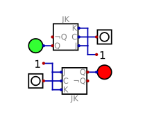
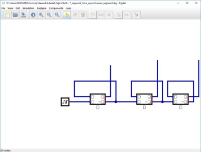
- Step 1: Construction of 3-bit asynchronous counter
As I have explained in my tutorial, we have to use three D-flip flops to constuct 3-bit asynchronous counter. (I highly recommend that reader should digest about the 3-bit counter tutorial,before moving into further steps.)
Completed version of the 3-bit counter should look like:
- Step 2: Configuration of outputs with respect to numbers
As a second step, we need to combine the outputs to have exact 8 output in the counter circuit, to do this operation we need to combine all of 3 outputs of counter such a way that each combination will represent a number for the 7-segment display. Overall operation should be in the following form.
For number 0 --> Q2'Q1'Q0'
For number 1 --> Q2'Q1'Q0
For number 2 --> Q2'Q1Q0'
For number 3 --> Q2'Q1Q0
For number 4 --> Q2Q1'Q0'
For number 5 --> Q2Q1'Q0
For number 6 --> Q2Q1Q0'
For number 7 --> Q2Q1Q0
Where Q2,Q1,Q0 represents the output of the 3-bit aysnchronous counter from the higher value to lower one,respectively, and ' represents NOT operation. I have used 3 input AND gates and 1 input NOT gates for this operation, and result should look like:
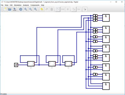
After this point, we managed to construct a circuit that represents each combination on counter outputs as a different output, so we are ready to implement our 7-segment display after this point.
- Step 3: Configuration of 7-segment display for the output of the circuits
This step is the most important step of the construction, we have to combine those outputs to visualize our circuit by the help of 7-segment display component. I have mentioned about the inputs and the corresponding LEDs of it, so that we have to connect this combination of this outputs to our 7-segment display successfully to have a correct circuit.
Operation process is given below:
7-segment LED#1 will be used by this numbers: 0,2,3,5,6
7-segment LED#2 will be used by this numbers: 0,1,3,4,5,6,7
7-segment LED#3 will be used by this numbers: 0,1,2,3,4,7
7-segment LED#4 will be used by this numbers: 0,2,3,5,6,7
7-segment LED#5 will be used by this numbers: 0,2,6
7-segment LED#6 will be used by this numbers: 0,4,5,6
7-segment LED#7 will be used by this numbers: 2,3,4,5,6
(Before moving forward in this tutorial, reader should understand the reason of those connections. It is highly recommend that check this connections and try to do without any help)
This connections are made by using OR gates in the software, unfortunately the software supports 5 input OR gates maximum, so in some cases I need to add second OR gate to make proper connections. I will skip the wiring steps, since I have already talked about in my previous steps, and it may confuse reader aswell.( Actually I gave the necessary connections in operation process part).
Finalized version of the circuit should look like : (and unfortunately it is a bit wire-chaotic)
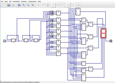
Again it is highly recommended that following those connections, and reader should try to make without any help to digest the topic better.
So, we are ready to observe our circuit.
- Episode 3: Simulation of the circuit
We are ready for simulation, results are shown below:
The results are expected.(please note that input 8 is just for the dot which reader can observe it on the given simulation)
I have provided the files for this tutorial here. I highly recommend that the reader should work on the files that I have provided and try to understand the basics of the circuit & software. It will be benefical for he/she.
This is the end for this tutorial.Hope that you like it.
Digital is a really effective and easy to learn software, I highly recommend this software for the one who wants to make simulation in digital circuits especially. If you have any questions, please feel free to ask me on Discord (Escorn#4114)
Curriculum
I have provided the previous tutorials that I have prepared for the community:
| SimulIDE | Caneda | Digital | LogiJS |
|---|---|---|---|
| Part 1 | Part 1 | Part 1 | Part 1 |
| Part 2 | Part 2 | Part 2 | |
| Part 3 | Part 3 | Part 3 | |
| Part 4 | Part 4 | Part 4 | |
| - | Part 5 | Part 5 | |
| - | Part 6 | Part6 | |
| - | Part 7 |
Posted on Utopian.io - Rewarding Open Source Contributors
Thank you for the contribution. It has been approved.
You can contact us on Discord.
[utopian-moderator]
Thank you :)
Hey @escorn I am @utopian-io. I have just upvoted you!
Achievements
Community-Driven Witness!
I am the first and only Steem Community-Driven Witness. Participate on Discord. Lets GROW TOGETHER!
Up-vote this comment to grow my power and help Open Source contributions like this one. Want to chat? Join me on Discord https://discord.gg/Pc8HG9x
Congratulations! This post has been upvoted from the communal account, @minnowsupport, by Escorn from the Minnow Support Project. It's a witness project run by aggroed, ausbitbank, teamsteem, theprophet0, someguy123, neoxian, followbtcnews, and netuoso. The goal is to help Steemit grow by supporting Minnows. Please find us at the Peace, Abundance, and Liberty Network (PALnet) Discord Channel. It's a completely public and open space to all members of the Steemit community who voluntarily choose to be there.
If you would like to delegate to the Minnow Support Project you can do so by clicking on the following links: 50SP, 100SP, 250SP, 500SP, 1000SP, 5000SP.
Be sure to leave at least 50SP undelegated on your account.