What Will I Learn?
- You will learn what a reed switch is and how to use it properly.
- You will learn how to integrate the reed switch with the arduino uno.
- You will learn how to program the arduino uno board that uses a reed switch and LED.
Requirements
Hardware
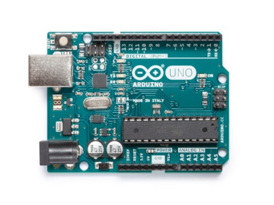
- Arduino Uno
- Reed switch

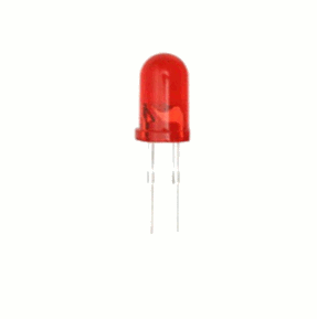
- LED
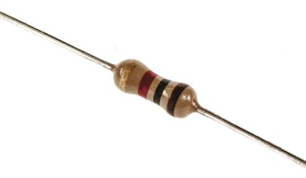
- Resistor (220 ohms)
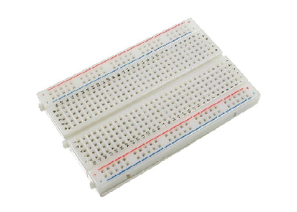
- Breadboard
- Jumper wires
- Computer

- USB type A to B cable
Software
- Arduino Software / Arduino IDE
Knowledge
- Basic electronics and programming knowledge
Difficulty
- Basic
Project description
- This is a simple project that is for beginners who want to know the basic operation of a reed switch and how it can be used with an arduino. The circuit is fairly simple, the reed switch is hooked to the arduino uno board, this will be its input sensor. The LED will be the output and will indicate the status of the switch. If the switch is closed the LED will turn ON and if the switch is open the LED will be OFF.
Component description
Arduino Uno - an arduino board that is regularly used by specialist and hobbyist because of its robust design. It is equipped with a microcontroller board that is based on ATMega328P with 14 advanced I/O pins (6 are PWM outputs), 6 analog inputs, 16 Mhz quartz crystal, a power jack, a USB port, an ICSP header and a reset button.
Reed switch - is basically a type of electrical switch that is operated by an applied magnetic field. It has a pair of ferromagnetic metal reeds as its contacts and is sealed with a glass. The reed switch is normally Open, once a magnetic field is applied to it the switch will close because the metal reeds will be attracted to the magnetic field causing them to stick together.

Tutorial Contents
Step 1: Gather the components
- You can buy the components in your nearby electronics shop or you can just order them online.

Step 2: Construct the Circuit
Connect the Sources
- Connect the 5V pin of the arduino uno board into the top/bottom slot of the breadboard. The connections here are horizontally connected making it an ideal spot for the sources.
- Connect the GND pin of the arduino uno board into the top/bottom slot of the breadboard but make sure not to short them out to avoid damaging the board.

Connect the Reed Switch
- The reed switch is non- polarized so it can be connected either way. Connect one leg of the switch into pin number 2 of the arduino board.
- Connect the other leg to the common ground(-) in the breadboard.

Connect the LED
- Connect the anode(+) of the LED to the 220 ohm resistor that is connected to pin number 4 of the arduino uno board. This resistor will protect the LED from the damage of over supply of current.
- Connect the cathode(-) of the LED to the common ground in the breadboard.

Step 3: Programming
- Connect the arduino uno board to the computer by using the USB type A to B cable.

- Once the connection is established, open the arduino IDE and go to Tools > Board: > then select Arduino/Genuino Uno.

- Copy the code below into your own sketch in the arduino IDE.
const int reedpin = 2; //sets the reed switch @pin 2
const int ledpin = 4; //sets the LED @pin 4
void setup()
{
  pinMode(reedpin, INPUT_PULLUP); //pull-up the reed switch pin internally
  pinMode(ledpin, OUTPUT);    //LED as the output
}
void loop()
{
  int proximity = digitalRead(reedpin); //reads the status of the reed switch
  if (proximity == LOW)   //if the reading is LOW,switch is closed
  {
    digitalWrite(ledpin, HIGH); //turns the LED ON
  }
  else
  {
    digitalWrite(ledpin, LOW); //turns the LED OFF
  }
}
What this code does is very simple, first it sets the pins of the reed switch and the LED then in the setup command, the reed switch at pin 2 is set to use the Arduino's internal pull-up resistor this will bias the switch HIGH, so when the switch closes it will connect the pin 2 directly to the ground and will be read as LOW. The LED at pin 4 is set as the OUTPUT. In the loop command, it is set to read the status of the reed switch. If it reads LOW, it indicates that the switch is closed and thus turning the LED ON, otherwise it will turn OFF the LED.
- After typing the code into your sketch, click the Verify button to save and compile the sketch. This will also check for any errors in the program.

- If no errors were found in the program, click the upload button to start programming the arduino board.

Step 4: Testing
- After the programming is finished, remove the arduino uno from the computer and connect it with a battery pack.
- Now, after the arduino uno board is active, get a piece of magnet and place it near the reed switch. This should turn the LED ON.
- Remove the magnet away from the reed switch, this should turn the LED OFF.
- If nothing is working, redo the previous steps carefully and make sure to follow it completely.
Curriculum
Here are my other arduino tutorials that might interest you:
- Arduino 101: Using a Force sensitive resistor to adjust an LED
- Arduino 101: Using a Gas sensor module
- Arduino 101: Controlling a solenoid lock
- Arduino 101: Alcohol sensor circuit using MQ-3 module
Posted on Utopian.io - Rewarding Open Source Contributors
Thank you for the contribution. It has been approved.
You can contact us on Discord.
[utopian-moderator]
Thank you very much @isfar :D
Hey @ted7 I am @utopian-io. I have just upvoted you!
Achievements
Suggestions
Get Noticed!
Community-Driven Witness!
I am the first and only Steem Community-Driven Witness. Participate on Discord. Lets GROW TOGETHER!
Up-vote this comment to grow my power and help Open Source contributions like this one. Want to chat? Join me on Discord https://discord.gg/Pc8HG9x
greetings excellent information are very good tutorials that you present in your account!
Thank you for reading my tutorials, I hoped you learned a lot from it. :)