
What is the project about?
The purpose of this work is to design a digital active single-phase power meter using the 18 series PIC microcontroller.
In this study 18F4620 was used as 18 series PIC. The software is in CCS C language.
The software also includes a day-to-day development of a single-phase digital active electricity meter and an example of a single-phase digital active electricity meter.
Technology Stack
- PIC C Compiler
- 20ms of sinus wave
- It is written with proper codes by taking 200 samples in 2ms intervals.
- Current information is shown with LCD.
Roadmap
- Introducing the system.
- Installing the system.
- Tell what the system is.
- Write codes with CCS C pic programming.
- Making the system work.
How to contribute?
- Report a bug,
- Send pull request,
- Send mail to me be a contributor.
- Feel free to ask anything, any language.
Single Phase Electricity Meter
Electricity meters are needed in homes, workshops, factories, in short, wherever power is wasted. The wasted power is a visual representation. Mechanical and electronic counters are divided into two. Mechanical meters are not used as of today.
Increasing sensitivity of the technology is increasing the usage of electronic meters.Despite the similarity of electronic meters with mechanical meters in terms of circuit connections and functions, the operating principles required for the structures are different from mechanical meters. In short, the operation of electronic meters,
the current and voltage information of the unit they are connected to can be described as the consumption information by transferring them to the LCD screen by using the electronic circuits to perceive and evaluate the information.However, unlike mechanical meters of electronic meters, it is also possible to observe the meter labels as well as the meter labels and the date, time, tariff information and number of external interventions.
General Features of the PIC18F4620 Microcontroller
The PIC 18F4620 carries the characteristics of the PIC 16F8XX family first. Harvard architecture was used in PIC 18F4620. In the Von Neuman architecture, access to the program memory and the data memory is made differently in this architecture, while the data and program memory can be accessed in the same way.
The databus is 8 bits wide. At the same time, when the data memory is accessed in this way 8 bits wide, the program memory is accessed by the program path or another 14-bit wide address path (program bus / address bus). The command codes (opcode) for PIC 16F87X and PIC 16F84 for this are 14 bits.
Each address of the 14-bit program memory corresponds to an instruction code (Instruction Code / Instruction Word). Each command is therefore accessed in a cycle and loaded into the command register. The command register is a register used by the CPU, and all commands, except branch commands, they are operated on the same cycle. Meanwhile, the program counter, PC (Program Counter) is an increment. The branching or diverting commands are executed in two consecutive cycles and the program counter PC is incremented by two.
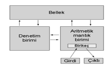
- The above figure Von Neumann architecture
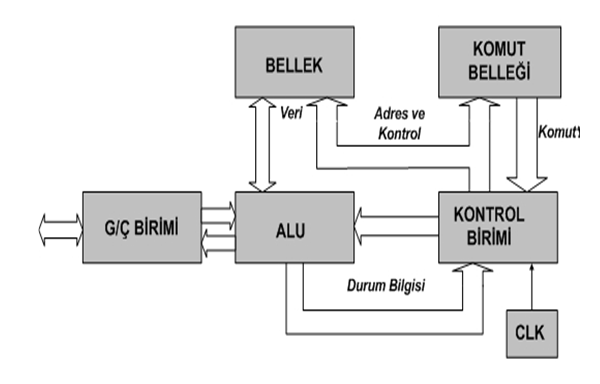
- The above figure Harvard architecture system
One of the most important subunits of the central processing unit (CPU) is the arithmetic logic unit called ALU (Arithmetic Logic Unit). The task of the ALU is to perform arithmetic or logical operations on the data sent to it. One of the ALU has two main inputs, the W (Working Register) being the name given to the register.
Two data (operators) that come to the ALU can be picked up and removed. It can do various logic operations (like, and, or, xor).
The most commonly used register in microprocessors is the "working register". This is called W for short. W executes two functions together in arithmetic and logic operations. Before the operation, it contains one of the operands.
After processing, it stores the result of the operation. In the PIC 18F4620 and 16F87X series microcontrollers, the microprocessor is reported to be held in W or other register with the number 1 or 0 placed at the end of the command (d).
Key Features of the 18FXXXX Microcontroller Family
- CPU reduced instruction set
- Uses Harvard architecture.
- Based on RISC.
- There are 75 commands to learn and each is 14 bits long.
- Branching instructions are applied in two cycles, while others are executed in one cycle.
- The processing speed is DC 40 MHz at 18F4620.
- Data bus (databus) is 8 bits.
- There are 32 special transaction registers called Special Function Registers (SFRs), which are on static RAM.
- Up to 64Kx14word flash memory can be programmed 1 million times.
- Increased data memory (RAM) up to 3968x8 Bytes,
- EEPROM data memory up to 1024 Bytes.
- Pin outputs compatible with PIC 16F877.
- Can cut from 14 sources.
- Stack depth is 8.
- Can make direct, indirect and relative addressing.
- Poweron Reset (System reset function when power is applied)
- Powerup Timer (Powerup timer)
- Oscillator Startup Timer (Oscillator start timer)
- Watchdog Timer (special type timer), in-line RC oscillator
- Ability to provide code safety with the program
- In-line Debugger (module that can be used for debugging)
- Low voltage programming
- Flash ROM program memory (EEPROM-enabled program memory)
- Energy-saving sleeping mode
- Optional oscillator features
- Parallel port control is possible.
- Low-power, high-speed, CMOSFlash EEPROM technology
- Totally static design
- 2 pin programmable feature
- 5V input only, in-line serial programming feature
- Access to the processor's program memory with read / write capability
- 2.0 V - 5.
- Wide operating range from 0 V
- 25mA welding current
- On-board, two pin debugging feature
- Ability to work in wide temperature range
- Low power operation
- Resistant to -40 ° C to 125 ° C under bias voltage
- It is between -65 ° C and 150 ° C.
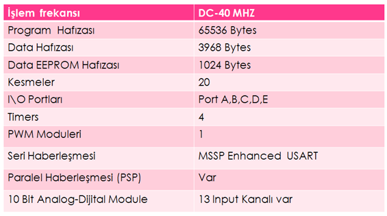
- The above figure Pic 18F4620's information
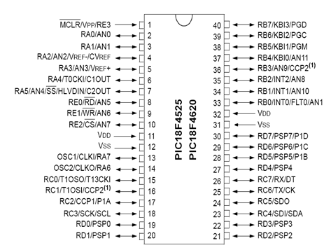
- The above figure Pic 18F4620 Leg Appearances
DS1302 Real Time Clock
DS1302; The RTC has a calendar and 31 bytes of RAM (battery protected). It communicates with the microprocessor through a simple serial interface. The real time clock (RTC) contains the day, minute, hour, day, month, year, day of the week, and date information until 2100. It can operate at voltages between 2.0 V and 5.0V. 2nd.
At 0 V, less than 300 nA of current is consumed. It has a burst or read mode for writing and reading in the clock and RAM memory. Compatible with TTL (Vcc = 5 V). - It can work between 40 ° C and + 85 ° C.
The DS1302 has two different inputs (VCC1, VCC2).
The DS1302 keeps its clock and time information in memory even when the battery is not energized by a battery connected to one of these terminals. When Vcc1 is at Vcc2 + 0.2V, the DS1302 feeds through Vcc1. Likewise, when the Vcc2 reaches Vcc1 + 0.2V or greater, the DS1302 automatically switches they start using the Vcc2 pin for supply voltage. All communications with the DS1302 begin with a command byte. The most significant bit (MSB) of the command byte must always be a logic "1".
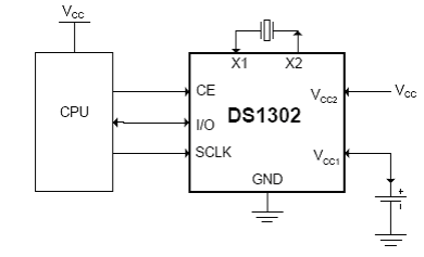
- The above figure DS1302 RTC leg connection
Voltage Transformer
- The transformer is a transformer. Figure 2. As shown in Figure 2, at least two separate coils wrapped around the same iron core (core) are formed. Wirewire primer receiving input voltage; the output voltage is called the secondary. Most of the time there are more secondary than two. The variable current ac voltage supplied to the primary creates a varying magnetic field in the iron core.
- This magnetic field, coupled to the secondary by the core, cuts off the secondary windings and induces an ac voltage across each windings. Thus, energy is transferred to the secondary from the primary by the changing magnetic field between them without any electrical connection.
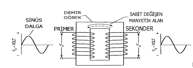
- The above figure Structure of the transformer
Current Transformer
The current transformer is a measure transformer that reduces the primary current to a secondary side within a certain ratio and the phase difference between the primary current and the secondary current is zero degrees. It provides isolation of the relays and measuring instruments from the high voltage system. The primer is connected to the serially connected coils, relay and measuring instruments.
The division of the primary circuit current into the secondary circuit current indicates the conversion factor of the current transformer. The second terminal in the current transformer connected to the system should never be open. Otherwise the current traf- fic will be damaged and undesirable situations may occur.
The secondary ends can be left in a short circuit state.
It is possible to find the current transformer as a relay mounted, busbar mounted, cable mounted and detachable body. A cable-mounted current transformer that converts 10A / 10mA is used in this project. The error margin of TEDAS is 0.5%.
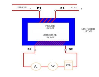
- The above figure Structure of the current transformer
.DS1302 CODES
#ifndef RTC_SCLK
#define RTC_SCLK PIN_C1
#define RTC_IO   PIN_C2
#define RTC_RST  PIN_C0
#endif
void write_ds1302_byte(BYTE cmd)
{
   BYTE i;
   for(i=0;i<=7;++i)
{
      output_bit(RTC_IO, shift_right(&cmd,1,0) );
      output_high(RTC_SCLK);
      output_low(RTC_SCLK);
   }
}


void write_ds1302(BYTE cmd, BYTE data)
 {
   output_high(RTC_RST);
   write_ds1302_byte(cmd);
   write_ds1302_byte(data);
   output_low(RTC_RST);
}

BYTE read_ds1302(BYTE cmd)
{
   BYTE i,data;
   output_high(RTC_RST);
   write_ds1302_byte(cmd);

   for(i=0;i<=7;++i)
{
      shift_right(&data,1,input(RTC_IO));
      output_high(RTC_SCLK);
      delay_us(2);
      output_low(RTC_SCLK);
      delay_us(2);
   }
   output_low(RTC_RST);
   return(data);
}

void rtc_init()
{
   BYTE x;
   output_low(RTC_RST);
   delay_us(2);
   output_low(RTC_SCLK);
   write_ds1302(0x8e,0);
   write_ds1302(0x90,0xa4);
   x=read_ds1302(0x81);
   if((x & 0x80)!=0)
     write_ds1302(0x80,0);
}

int get_bcd(BYTE data)
{
   int nibh;
   int nibl;
   nibh=data/10;
   nibl=data-(nibh*10);
   return((nibh<<4)|nibl);
}

int rm_bcd(BYTE data)
{
   int i;
   i=data;
   data=(i>>4)*10;
   data=data+(i<<4>>4);
   return data;
}

void rtc_set_datetime(BYTE day, BYTE mth, BYTE year, BYTE dow, BYTE hr, BYTE min)
{
   write_ds1302(0x86,get_bcd(day));
   write_ds1302(0x88,get_bcd(mth));
   write_ds1302(0x8c,get_bcd(year));
  write_ds1302(0x8a,get_bcd(dow));
   write_ds1302(0x84,get_bcd(hr));
   write_ds1302(0x82,get_bcd(min));
   write_ds1302(0x80,get_bcd(0));
}

void rtc_get_date(BYTE& day, BYTE& mth, BYTE& year, BYTE& dow)
{
   day = rm_bcd(read_ds1302(0x87));
   mth = rm_bcd(read_ds1302(0x89));
   year = rm_bcd(read_ds1302(0x8d));
   dow = rm_bcd(read_ds1302(0x8b));
}

void rtc_get_time(BYTE& hr, BYTE& min, BYTE& sec)
{
   hr = rm_bcd(read_ds1302(0x85));
   min = rm_bcd(read_ds1302(0x83));
   sec = rm_bcd(read_ds1302(0x81));
}

void rtc_write_nvr(BYTE address, BYTE data)
{
   write_ds1302(address|0xc0,data);
}

BYTE rtc_read_nvr(BYTE address)
{
    return(read_ds1302(address|0xc1));
}
- I turned on the electricity meter. And I exhibited a product design with integrated pic. I explained some hardware parts. Now we will build the system with the LCD Code.
Shunt Resistance
- The resistance that the electric current passes over is the resistance. The current from the current transformer passes through this resistor. This resistance of 100.3 ohms reads the voltage on it and shows it in amps on a scale calculated according to V = I * R (voltage equalized current multiplied resistance formula).
- This resistor, which is connected in series, makes the voltage drop in the place to be used. The value of the shunt resistor is very small, so the voltage drop is too small and is not taken into consideration.
Lithium Battery
- Rechargeable lithium batteries have the highest energy density within conventional rechargeable battery systems. From this perspective,these batteries can store more energy in a given volume or weight than other batteries. The lithium battery is produced in the same cylindrical and prismatic form as other batteries.
- However, prismatic type batteries, they are more suitable to place in battery blocks in terms of their shape than cylindrical types. The nominal voltage of the lithium battery is 3.6V. This is 3 times that of Ni-Cd and Ni-MH batteries. For this voltage compatibility, 3 Ni-Cd or Ni-
One lithium battery can be used instead of the MH battery (but the charging system must be considered in other parameters, such as the current requirement of the device the battery is running on).
Bridge Rectifier
The bridge rectifier is actually a full-wave rectifier, and only the input voltage source is not zero-centered like a full-wave rectifier, powered by a single AC source. Bridge Rectifier is seen as below
- Bridge Diodes can be made with four diodes, and four diodes are sold in the market together with the merged shape. Let's apply an alternating voltage to the input of the above circuit (between the e-f terminals).
- The input voltage which starts to rise in the positive direction from time t1 will make the a-terminal positive and the b-terminal negative. This diode will be positive for diode D1, diode for diode A, and anode for diode D3 will be positive. In the same way, the diode of diode D2 will be negative and the anode of diode D4 will be negative. Note that D1-
- A load resistor is connected between the junction of the cathodes of the D4 diodes and the junction of the anodes of the D3-D2 diodes. (The load resistor can be an electronic circuit that we use, or it can be a resistor with its shape.) With the positive diode D1, a current starts to flow through the negative diode D2. Since the flowing current enters the upper end of the load resistor and goes out at the end of the load, the upper end of the load resistor will be positive and the lower end will be negative. The current flowing through the diodes D1 and D2 flows through the time t1-t2, that is,
It will continue as long as point b is negative.
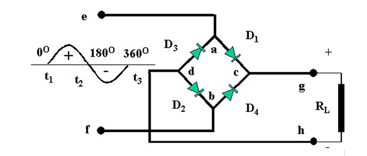
- Bridge Type Rectifier
7805 Circuit
- The most important features of integrated regulators are their small size and they can give different output voltages at different input voltages. Regulated circuits are circuits with regulated circuits. This statement, if used for a rectifier: means "circuit which holds the output voltage or current constant at a certain value". At the same time, the words "regulating circuit" or "regulator" are used.
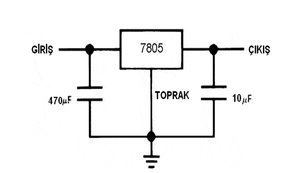
7805 connection
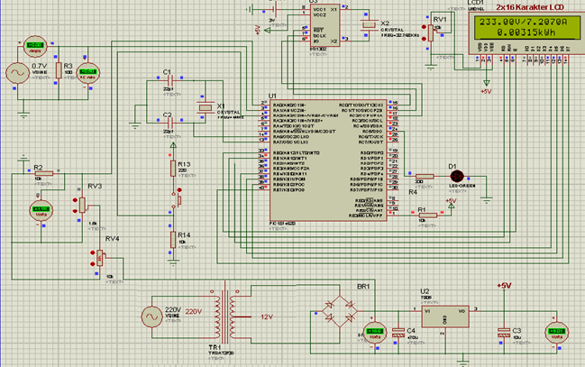
The design was developed in stages. First of all, it is to detect the voltage drop to 18F4620 using 4W 220V / 12V voltage transformer rotating method. Then, with a 10A / 10mA current transformer, the shunt resistor is used to sense current information to 18F4620.
The read current and voltage information is displayed on the LCD in kilowatt-hours by making appropriate calculation operations.
CIRCUIT DESIGN AND EQUIPMENT OF PIC18F4620 ONLY DIGITAL ACTIVE ELECTRIC COUNTER
In this study, a 4W 220V / 12V voltage transformer was used with a 12V AC bridge diode,
It is turned to 8V DC value. A constant 5V voltage was obtained by connecting 7805 to the bridge diode output. The 5V constant voltage is connected to the supply terminals of the 18F4620. Half-wave rectifier was made by connecting a 1uF capacitor to the negative terminal of the diode by connecting the In4001 diode to the bridge diode plus terminal. To do half-wave rectification,
to destroy the AC components of the bridge diode and reduce the output voltage of the bridge diode by 0.7V. The voltage divider resistors to which In4001 is connected to the negative terminal are added to the circuit to not exceed the maximum 5V value of 18f4620.To read the voltage information, the voltage value from the voltage divider is given to analogue terminal A0 of 18F4620. The value on the analogue end of the 18F4620 is digitally converted by the ADC conversion on the internal side. The read digital value is written with the appropriate codes by using PIC C Compiler program, taking 200 samples in 2ms interval of 20ms sinus wave.
Voltage information is shown with LCD.To read current information. The voltage information read on the shunt resistor is given to the analogue terminal A1 of 18F4620. The value on the analogue end of the 18F4620 is digitally converted by the ADC conversion on the internal side. With the help of the PIC C Compiler program,
The 20ms sinus waveform is written with appropriate codes by taking 200 samples at intervals of 2ms. Current information is shown with LCD.The momentary power draws are calculated in kilowatt hours by performing an operation in 1 second with appropriate calculations of instantaneous voltage drops and instantaneous currents. The previous strength,
The 18F4620 stores its past power by recording to EEPROM. It records by adding on the forces drawn later. The spent energy is shown in kilowatt-hour with LCD.
LCD CODE
#define use_portb_lcd TRUE
  #include <lcd.c>

  int x;
  float y;
  char z;

  set_tris_b(0x00);
  lcd_init();
  x=06228027;
  y=22.10;

  while(1)
  {
   lcd_send_byte(0,0x0d);
   print(lcd_putc,"\f     CCS C");
   delay_ms(1000);
   printf(lcd_putc,"\n    DERLEYICISI");
   delay_ms(1000);
   lcd_gotoxy(1,2);
   print(lcd_putc,"\f X DEGERI:%d",x);
   delay_ms(1000);
   printf(lcd_putc,"\f\n Y DEGERI:%f",y);
   delay_ms(1000);
   printf(lcd_putc,"\f DIRENC");
   delay_ms(1000);

   z=lcd_getc(4,1);

   printf(lcd_putc,"\f Z=%c",z);
   delay_ms(3000);
  }
Considering the external elements required for the PIC18F4620, the elements used are listed below, the circuit diagram is show figure 4.1 and the installed circuit is shown in photo 4.1.
- PIC18F4620 microcontroller
-Crystal oscillators of 4 Mhz and 32,786 Khz - Two 22pF, 1uF, 10uF, and 1000uF capacitors
- Four 10Kohm, 330ohm,
- 200 ohm resistors
- IN4001 diode
- 11W 100 ohm shunt resistor
- Green led
- 5Kohm potentiometer
- DB104S bridge diode integration
- DS1302 RTC integration
- LCD display
- Reset, On-off buttons,
- 220V / 6V voltage transformer
-10A / 10mA current transformer - 3.6V lithium battery
- Plug, Triple socket
- 70 cm 2.5 mm2 cable
- 20x18cm connection box
-7805
CODES OF SINGLE PHASE DIGITAL ACTIVE ELECTRIC COUNTER
#include <18F4620.h>
#fuses XT,NOWDT,NOPROTECT,NOBROWNOUT,NOLVP,NOPUT,NOWRT,NODEBUG,NOCPD
#use delay(clock=4000000)
#use fast_io(a)
#use fast_io(b)
#use fast_io(c)
#define use_portb_lcd TRUE
#include <LCD.C>
#include <math.h>
#include <DS1302.c>
unsigned long int vbilgi,abilgi;
float voltaj,vtop,atop,gtop,volt,akim,amper,guc,vkare,akare,deger;
int i,j;
byte saniye,dakika,saat,gun,ay,yil,haftanin_gunu;
void main()
{

   setup_adc_ports(AN0_TO_AN2|VSS_VDD);
   setup_adc(ADC_CLOCK_DIV_2|ADC_TAD_MUL_0);
   setup_psp(PSP_DISABLED);
   setup_spi(SPI_SS_DISABLED);
   setup_wdt(WDT_OFF);
   setup_timer_0(RTCC_INTERNAL);
   setup_timer_1(T1_DISABLED);
   setup_timer_2(T2_DISABLED,0,1);
   setup_timer_3(T3_DISABLED|T3_DIV_BY_1);
   setup_comparator(NC_NC_NC_NC);
   setup_vref(FALSE);
   lcd_init();
   rtc_init();  // DS1302 başlangıç ayarları yapılıyor
   set_tris_a(0x07);
   set_tris_b(0x00);
   set_tris_c(0x00);
   rtc_set_datetime(24,04,07,6,22,42); // Tarih ve Saat ayarları yapılıyor

while(1)
{

      rtc_get_time(saat,dakika,saniye);
      rtc_get_date(gun,ay,yil,haftanin_gunu);
      printf(lcd_putc,"\f %02d/%02d/20%02d ",gun,ay,yil);

      switch(haftanin_gunu)
      {
         case 1: printf(lcd_putc,"PAZ"); break;
         case 2: printf(lcd_putc,"PZT"); break;
         case 3: printf(lcd_putc,"SAL"); break;
         case 4: printf(lcd_putc,"CRS"); break;
         case 5: printf(lcd_putc,"PER"); break;
         //case 6: printf(lcd_putc,"CUM"); break;
         case 7: printf(lcd_putc,"CTS"); break;
      }
      printf(lcd_putc,"\n  %02d:%02d:%02d",saat,dakika,saniye);

      deger=0.0048828125;
       for(i=0;i<200;i++)
       {
         set_adc_channel(0);
         delay_us(20);
         vbilgi=read_adc();
         volt=deger*vbilgi;
         vkare=volt*volt;
         vtop=vtop+vkare;
         delay_us(1970);
       }
         output_high(pin_c5);
         voltaj=vtop/200;
         voltaj=sqrt(voltaj);
             {
               if(voltaj>=1.950 && voltaj<1.960)
               {
               voltaj=voltaj*123.0769231;
               }
               if(voltaj>=1.940 && voltaj<1.950)
               {
               voltaj=voltaj*123.1958763;
               }
               if(voltaj>=1.930 && voltaj<1.940)
               {
               voltaj=voltaj*123.3160622;
               }
               if(voltaj>=1.9200 && voltaj<1.930)
               {
               voltaj=voltaj*123.4375;
               }
               if(voltaj>=1.910 && voltaj<1.920)
               {
               voltaj=voltaj*123.5602094;
               }


               if(voltaj>=1.900 && voltaj<1.910)
               {
               voltaj=voltaj*123.6842105;
               }
               if(voltaj>=1.890 && voltaj<1.900)
               {
               voltaj=voltaj*123.8095238;
               }
               if(voltaj>=1.880 && voltaj<1.890)
               {
               voltaj=voltaj*123.9361702;
               }
               if(voltaj>=1.870 && voltaj<1.880)
               {
               voltaj=voltaj*124.0641711;
               }
               if(voltaj>=1.860 && voltaj<1.870)
               {
               voltaj=voltaj*124.1935484;
               }
               if(voltaj>=1.850 && voltaj<1.860)
               {
               voltaj=voltaj*124.3243243;
               }
               if(voltaj>=1.840 && voltaj<1.850)
               {
               voltaj=voltaj*124.4565217;
               }


               if(voltaj>=1.830 && voltaj<1.840)
               {
                 voltaj=voltaj*124.5901639;
               }
               if(voltaj>=1.820 && voltaj<1.830)
               {
               voltaj=voltaj*124.7252747;
               }
               if(voltaj>=1.810 && voltaj<1.820)
               {
               voltaj=voltaj*124.8618785;
               }
               if(voltaj>=1.800 && voltaj<1.810)
               {
               voltaj=voltaj*125;
               }
               if(voltaj>=1.790 && voltaj<1.800)
               {
               voltaj=voltaj*125.1396648;
               }
               if(voltaj>=1.780 && voltaj<1.790)
               {
               voltaj=voltaj*125.2808989;
               }
               if(voltaj>=1.770 && voltaj<1.780)
               {
               voltaj=voltaj*125.4237288;
               }


               if(voltaj>=1.760 && voltaj<1.770)
               {
               voltaj=voltaj*125.5681818;
               }
               if(voltaj>=1.750 && voltaj<1.760)
               {
               voltaj=voltaj*125.7142857;
               }
               if(voltaj>=1.740 && voltaj<1.750)
               {
               voltaj=voltaj*125.862069;
               }
               if(voltaj>=1.730 && voltaj<1.740)
               {
               voltaj=voltaj*126.0115607;
               }
               if(voltaj>=1.720 && voltaj<1.730)
               {
               voltaj=voltaj*126.1627907;
               }
               if(voltaj>=1.710 && voltaj<1.720)
               {
               voltaj=voltaj*126.3157895;
               }
               if(voltaj>=1.700 && voltaj<1.710)
               {
               voltaj=voltaj*126.4705882;
               }


               if(voltaj>=1.690 && voltaj<1.700)
               {
               voltaj=voltaj*126.6272189;
               }
               if(voltaj>=1.680 && voltaj<1.690)
               {
               voltaj=voltaj*126.7857143;
               }
               if(voltaj>=1.670 && voltaj<1.680)
               {
               voltaj=voltaj*126.9461078;
               }
               if(voltaj>=1.660 && voltaj<1.670)
               {
               voltaj=voltaj*127.1084337;
               }
               if(voltaj>=1.650 && voltaj<1.660)
               {
               voltaj=voltaj*127.2727273;
               }
               if(voltaj>=1.640 && voltaj<1.650)
               {
               voltaj=voltaj*127.4390244;
               }
               if(voltaj>=1.630 && voltaj<1.640)
               {
               voltaj=voltaj*127.607362;
               }


               if(voltaj>=1.620 && voltaj<1.630)
               {
               voltaj=voltaj*127.7777778;
               }
               if(voltaj>=1.610 && voltaj<1.620)
               {
               voltaj=voltaj*127.9503106;
               }
               if(voltaj>=1.600 && voltaj<1.610)
               {
               voltaj=voltaj*128.125;
               }
               if(voltaj>=1.590 && voltaj<1.600)
               {
               voltaj=voltaj*128.3018868;
               }
               if(voltaj>=1.580 && voltaj<1.590)
               {
               voltaj=voltaj*128.4810127;
               }
               if(voltaj>=1.570 && voltaj<1.580)
               {
               voltaj=voltaj*128.6624204;
               }
               if(voltaj>=1.560 && voltaj<1.570)
               {
               voltaj=voltaj*128.8461538;
               }


               if(voltaj>=1.550 && voltaj<1.560)
               {
               voltaj=voltaj*129.0322581;
               }
             }
             voltaj=floor(voltaj);

         for(j=0;j<200;j++)
       {
         set_adc_channel(1);
         delay_us(20);
         abilgi=read_adc();
         akim=deger*abilgi;
         akare=akim*akim;
         atop=atop+akare;
         delay_us(1970);
       }

         amper=atop/100;
         amper=sqrt(amper);
         amper=amper+amper/75.2;
         amper=amper*10;
      printf(lcd_putc,"\f%fV/%0.4fA",voltaj,amper);
      delay_us(100);
         guc=voltaj*amper;
         guc=guc/3600000;
         gtop=gtop+guc;
      printf(lcd_putc,"\n   %0.5fkWh",gtop);
         write_eeprom(0,gtop);
         output_low(pin_c5);
              akim=0;
              amper=0;
              abilgi=0;
              atop=0;
              vkare=0;
              voltaj=0;
              vbilgi=0;
              vtop=0;
        delay_ms(1000);
 }
}
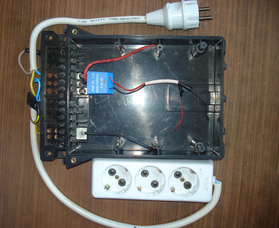
- Photo 4.1. Current Transformer
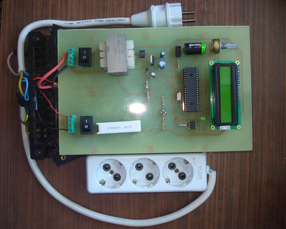
- Photo 4.2. Single Phase Counter Circuit Design and Hardware
Yes First we installed our system. We created the circuits. And we wrote the software. and we now have a single-phase electricity meter.
Posted on Utopian.io - Rewarding Open Source Contributors
Your contribution cannot be approved because it does not follow the Utopian Rules.
You previous contribution has been rejected.
https://utopian.io/utopian-io/@ussimsek/single-phase-electricity-meter-or-system-installation-and-promotion
Simply re-submitting it does not work. We discussed this long and hard.
You can contact us on Discord.
[utopian-moderator]