I could not find any detailed diagram of how to install a 3-way Wifi Light System (ON/OFF) (2 light switches connected to same set lights) or 4-way Wifi Light System (ON/OFF) (3 light switches connected to same set lights) in a hallway e.g. 1 switch on far end of hallway, 1 in the middle and 1 on the near end for convenience.
When I figured this out the Wifi 4-way light switches installation was actually easier than expected compared to traditional manual light switches wiring.
I will be using Sonoff / ITEAD 4x2 Luxury Glass Panel Wifi Light Switches with Single Button (Also called 1 Gang Switch) as examples for a 4-way Light System.
Tools I used:
• Small Phillips Screwdriver for Sonoff screws
• Side Cutters for Cutting Wires (May not be needed)
• Cheap Multimeter capable of detecting AC Voltages – Used for testing where live wires are connected to Power Distribution Board.
• Tone and Probe – Also called Cable Tracker / Tracer – These costs around $ 25- $30. Only needed if you cannot find or do not know which wire is the live wire from your distribution board.
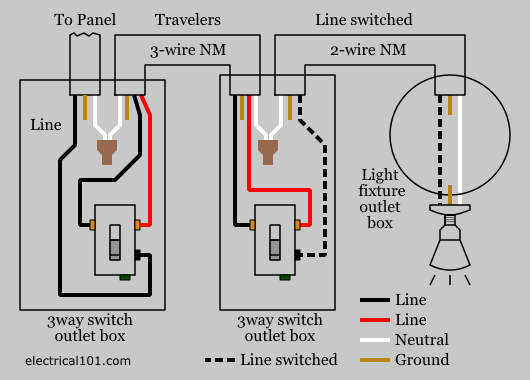
A traditional 4-way Manual Light switch diagram below. It is much more complex than installing Wifi Light Switches.
Important to remember: The Sonoff / ITead WIFI Light Switches (or any other WIFI Light Switch) always need power to ensure connection to the Wifi network. This is where the wiring differs since on traditional manual light switches in a 4-way setup there is not always power to a specific input depending on the status of other switches.
Example of a Single Wifi Light Switch wiring diagram (Sonoff 4x2 Luxury Glass Panel Wifi Light Switch Below)
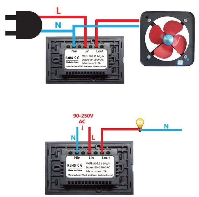
In our country we use 220 Volt and I will use this as an example and reference. Other Countries uses 110-115 volt but it does not matter the wiring and principal is the same.
For the example I will show you how to wire a 4-Way Wifi Light Switch System (3 Switches connected to the same set of lights)
Step 1: Determine where your Live wire is connected from the Power Distribution board.
IMPORTANT: Make sure your Light power breaker for the specific set of lights is OFF at the power distribution board when doing any wiring changes.
If you already know where your Live wire from Power Distribution Board is you can skip this step.
Make sure light breaker is OFF at power distribution board and disconnect all wiring from current manual light switches.
The wires MUST NOT touch each other and are far away from each other. Make sure it is not reachable by children or any person during a power test!!
I will use the wire colour codes in our Country when Referring to Live = Red (or sometimes Brown), Neutral = Black, Ground = Green/White and Runner Cables can be any colour normally Pink in our country
Switch ON the Light breaker on the Distribution Board.
Use the Multimeter and set it to Voltage AC 200v+. My Multimeter for example has an 800v setting to test AC voltages up to 800v.
Now ensure you know how to use a Multimeter before doing these tests. NEVER touch the metal points and keep the plastic handles of the Multimeter in your hands only.
Each of the 3 manual light switches will have a Neutral and Live wire which are now disconnected from the switches and hanging loose. The Neutral may be disconnected or cut-off by the installer who installed the light switches due to not needed on manual light switches for some of the switches. You will have to find this neutral wire at all the switches outlets.
Press the Red Pole of the Multimeter on a Live Colour cable and the Black Pole of the Multimeter on a Neutral Colour cable. Refer to colours explained above.
Each light switch cables needs to be tested until you find one that gives a reading of 220-230 volt (Or whichever volts are used in your country). This will be the outlet where Live enters from the Power Distribution Board.
The other end of the hall switch outlet will have the live wire that runs to Lights but this can be easily found when all wires are connected as per 4-Way Wifi wiring diagram below. It will be the remaining Live wire when All Lin Live wires connected below. You can also use the Cable tracer to find the correct wire ends.
Step 2 : Wiring the Wifi Switches
NOW ENSURE THE LIGHT BREAKER IS OFF AT DISTRIBUTION BOARD BEFORE PROCEEDING WITH ANY WIRING.
The Wifi Light Switches wiring will look odd when first examined until you read the section of Wifi Scenes explained, Since 2 of the Wifi Light switches will not actually break / pass the live wire to a load / sets of lights. They are only used for convenience at locations of your choice to set a status to On/Off where traditional light switches will pass load.
Wire the 3 x Sonoff Wifi Light Switches as below. NOTE: You can use any wire between light switches to loop the live wire from Power Distribution Board to All Light Switches. Neutral Wires needs to be connected to each other as well. There will be additional “Runner” Cables if manual light switches are already installed which you can use to loop the Live from one light switch to another. You will need the Cable Tracer tool to find which cable end is connected to which end between switches. Runner cables are normally Pink.
As you can see from diagram this will ensure all Wifi Light Switches has live and Neutral Power to Them to ensure always connected to Wifi Network and Wifi Always active.
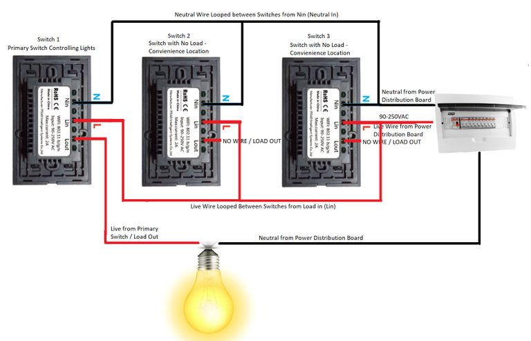
Currently ONLY Switch 1 above will control your lights On/Off Status. Switch 2 and Switch 3 will have no function to control the lights until some scenes are created as below.
Install the app used for your light switches – I use the default app EWELINK supplied and working with the ITEAD / Sonoff Light Switches and it can be downloaded from the Android Play Store for Android Phones.
Ensure the breaker is ON at the Power Distribution Board.
Pair all Light switches as per instructions of the manufacturer to your Wifi network. (Normally by pressing and holding On/Off switch for a few seconds until light constantly flashes and then pairing with EWELINK App)
You will have to create a few once-off conditions / scenes to ensure your lights function as expected. These scenes will also automatically apply if the touch button used on the Wifi Light switches ON or OFF or when controlled from your smartphone. Name it as below SCENE 1 ON, SCENE 2 ON etc.
- Open the EWELINK App
- Create SCENE 1 ON : Tap on Scene
- Tap on +Scene
- Tap Condition +Add and Choose Switch 1 - Primary Light Switch as in diagram controlling the lights (Whatever name you gave it) and Condition = ON.
- Go Back and click Perform +Add Switch 2 = ON, Save and Repeat Perform +Add and Switch 3 = ON
This Scene will ensure All Light Switches are ON when Switch 1 Used.
Repeat above and create TWO more scenes as below
SCENE 2 ON: +Scene Choose Condition+Add and Choose Switch 2=ON and then Perform +Add Switch 1 = ON, Save and Repeat Perform +Add and Switch 3 = ON
SCENE 3 ON: +Scene Choose Condition+Add and Choose Switch 3=ON and then Perform +Add Switch 1 = ON, Save and Repeat Perform +Add and Switch 2 = ON
SCENE 1, SCENE 2 & SCENE 3 ABOVE will ensure all light switches ON when ANY of the light switches are ON, ensuring the Primary Switch 1 switches the Lights on from any switch.
Now the above 3 scenes will need to be recreated for when switching the lights OFF as below. Name the Scenes SCENE 1 OFF, SCENE 2 OFF as example.
SCENE 1 OFF: +Scene Choose Condition+Add and Choose Switch 1=OFF and then Perform +Add Switch 2 = OFF, Save and Repeat Perform +Add and Switch 3 = OFF
SCENE 2 OFF: +Scene Choose Condition+Add and Choose Switch 2=OFF and then Perform +Add Switch 1 = OFF, Save and Repeat Perform +Add and Switch 3 = OFF
SCENE 3 OFF: +Scene Choose Condition+Add and Choose Switch 3=OFF and then Perform +Add Switch 1 = OFF, Save and Repeat Perform +Add and Switch 2 = OFF
The six scenes above will ensure all switches ON when ANY switch ON and ALL Switches OFF when ANY Switch OFF.
Your Light System will now correctly function as a 4Way Wifi Light System. Above can be used for a 3-Way Light System (2 Wifi Light Switches) as well and will require less Scenes to be created.
Congratulations @thiartj! You received a personal award!
Click here to view your Board
Congratulations @thiartj! You received a personal award!
You can view your badges on your Steem Board and compare to others on the Steem Ranking
Vote for @Steemitboard as a witness to get one more award and increased upvotes!