ENGLISH
Greetings to the entire community, once again it is a pleasure to be here sharing my experiences with you. I tell you that recently I was given one of those situations at home in which several computers break down almost at the same time, or with a very short time interval and put you to run. The thing is that I have two televisions, one in the living room that is used mostly by my grandfather and another in my room, which is the one I use. Each TV is connected to a Digital Terrestrial Television (DTT) decoder, however both decoders broke down leaving us practically without being able to watch TV, because although there is still the possibility of watching analog television, the truth is that there are only four or five analog channels depending on the region of the country, so we are limited to only watch those channels.
So I set myself the task of repairing as quickly as possible the two DTT decoders, and later I will tell you what were the failures and how I solved them.
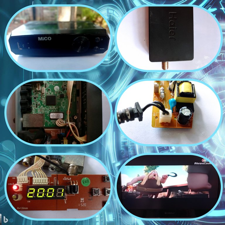
First I will show you the two DTT Decoders.
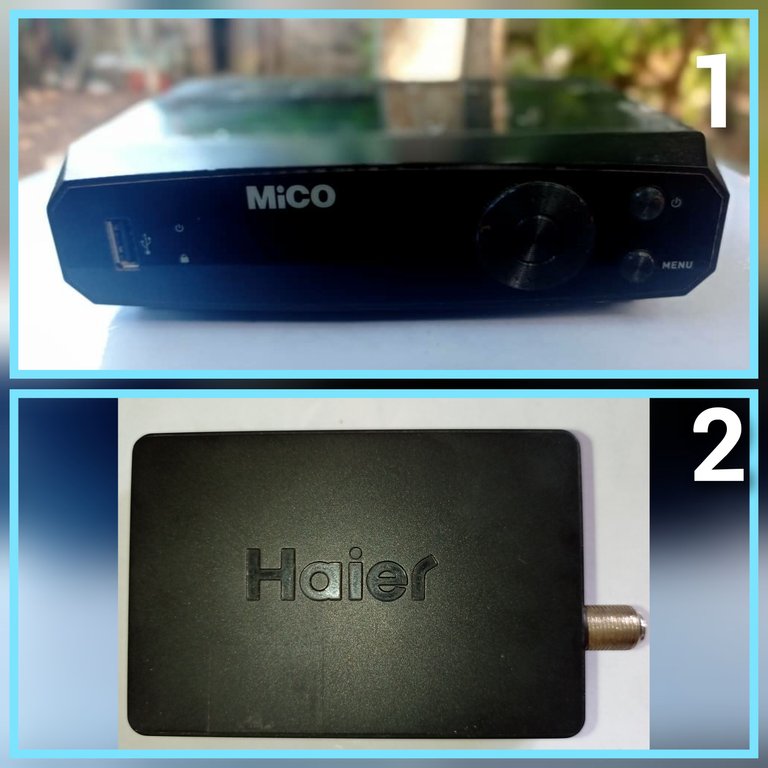
1- Mico_DTMB_DT46
2- Haier HDMB-2000t/m
Failure analysis and repair of the DVB-T decoder connected to the TV in the living room (1)
The symptom of this decoder is that it did not show video through the RCA output that connects to the TV, in addition to the fact that none of the LED indicators or the seven segments panel that show the on or off status of the decoder lit, however when connecting it to the AC outlet there was a color change on the TV that showed me that the decoder was trying to turn on but at all times the screen remained black, that is, the color change on the screen was from a deep black to a lighter one, but at no time did it show any image.
DISASSEMBLING THE DECODER
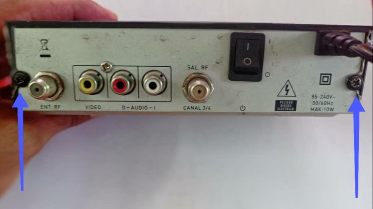
This particular decoder is disassembled by removing the screws shown in the image with the arrows.
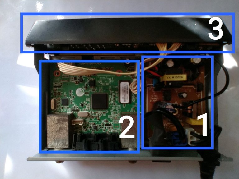
After removing the cover you can see three main blocks inside the decoder
1- Switching power supply that provides the 5 volts of direct current that feeds the main board.
2- Main board where, in general, the DTT signal processing takes place.
3- Front panel where the different LED indicators are present, for example: On/Off indicator, seven segments panel and infrared LED that receives the signals from the remote control.
THE FIRST THING TO DO WHEN REPAIRING ANY EQUIPMENT.
When we repair an equipment the first step is to make a good visual inspection of the equipment, sometimes the failures are manifested physically in the surfaces of the components or electronic boards, example: deformation of the component, changes of coloration, cold welds, broken connections, blows etc. By detecting any of these physical features on the board we can greatly facilitate the repair.
At first glance when checking the decoder boards, no physical alterations as described above were observed. However looking carefully and taking as experience other repairs in which the failure has been originated by the corrosive action of certain glue that some manufacturers use in the electronic boards to fix some components, I stopped in the front panel board, which had this glue that supposedly gave firmness to a capacitor, when removing the glue my suspicions were confirmed as I show in the following images.
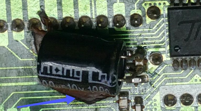
This image was taken on another decoder by the user @Tloarreglo from the group CACHARREROS de Cuba on the social network Telegram, to whom I asked for authorization to show his photo in this post, in order to show the glue I referred to above, because I did not take photos on my decoder before removing said glue.
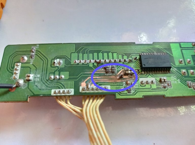
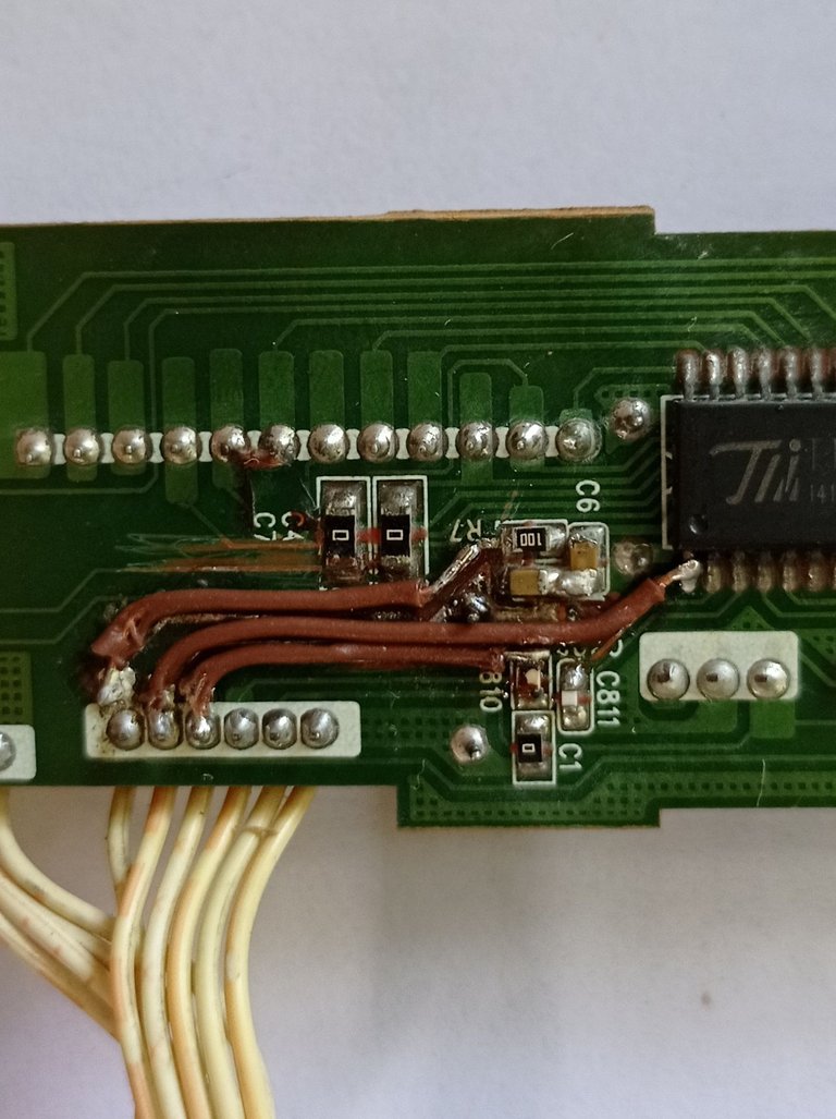
Here you can see how when I removed the glue and scraped well the lanes I detected that they were interrupted due to the corrosion of the glue.
Note: This glue apparently has chemical components that have a corrosive action on the copper of the connections of the board, however the manufacturers continue using it. My opinion is that they do it intentionally because I doubt very much that they do not have knowledge of the damage it causes to the boards, it is slow but sure. Whenever I see it I think of a topic in electronics today: Programmed Obsolescence, and although I am not sure that the use of this substance is part of this topic of Obsolescence, the truth is that it is a time bomb that is perfectly convenient for manufacturers.
My advice: whenever you see it, remove all the glue and clean the area well with some electronic cleaner, or alcohol, if it is isopropyl much better.
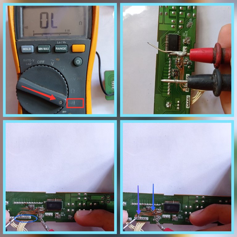
Although at first glance you can see three interrupted streets, it is better to check that there is continuity between each point marked inside the blue oval with its corresponding connection point, as indicated with the arrows, for this I used the multimeter in continuity scale (indicated in the first image of the collage), black tip of the multimeter in the connection points marked inside the oval and red tip at the end of each street, it is checked point by point that there is continuity.
In my case there were only three streets in bad condition and they were the ones that can be observed with the naked eye.
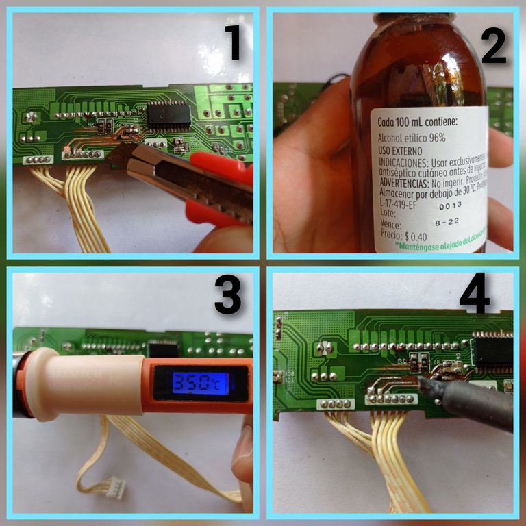
1- With the help of a cutter I carefully scraped the streets in bad condition.
2- I applied 96% alcohol to clean the area well with a toothbrush and remove the remains of the glue that damaged the lanes.
3- I regulated my soldering iron to 350°C.
4- I applied tin to the fairways to later bridge them with fine wires as shown in the following image.
Streets bridged with fine wires.
After bypassing the streets and testing the decoder thinking that the problem would be solved, I realized that there was still another fault as the front panel would not turn on, so I continued searching and discovered that when I connected the front panel, the 5 volt voltage coming from the switching power supply dropped to 0.8 volts. This means that there was an over consumption produced by a short circuit.
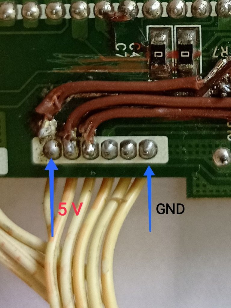
With the multimeter on continuity scale and the board disconnected from the source, I measured between the 5 volt input terminal and the ground terminal (GND), giving a continuity reading that evidences a short circuit between the 5 volts and ground, so I had to check all the components associated with the 5 volt line.
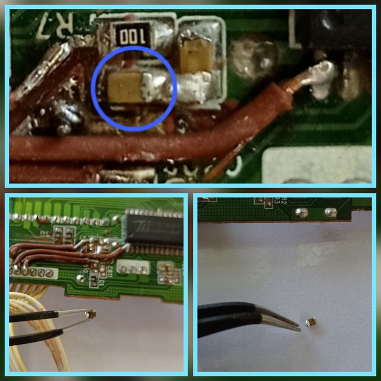
After making several measurements and discarding the components in good condition, I managed to find the culprit, which was the smd capacitor that I show in the photo, it was internally shorted, this usually happens with these smd capacitors, they tend to short circuit, disabling equipment completely.
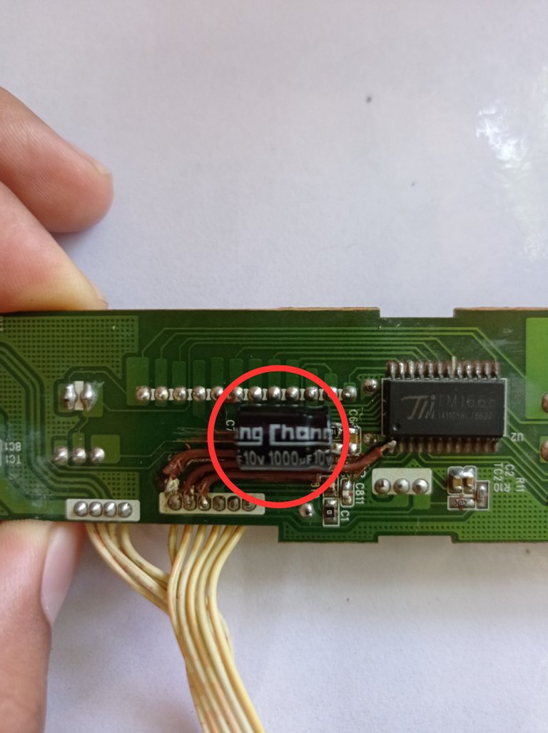
I replaced the short smd capacitor with a similar one in good condition, I also re-soldered the electrolytic capacitor (marked in a red circle) that I had to remove at the beginning to work more comfortably on the board.
READY!!! IT'S TIME TO TEST THE BOARD AGAIN....
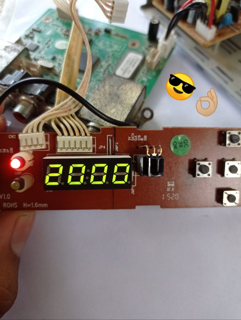
I reconnected the front panel connection plug, powered the decoder and this was the result, working ok to my pleasant surprise.
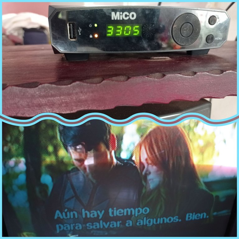
I then reassembled the DTT decoder exactly as it was before I took it apart, connected it to the TV, and these were the final results.
One piece of equipment repaired, now the other one is missing...
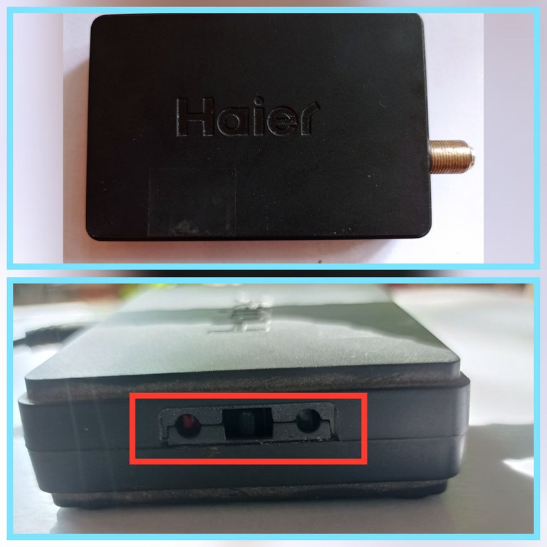
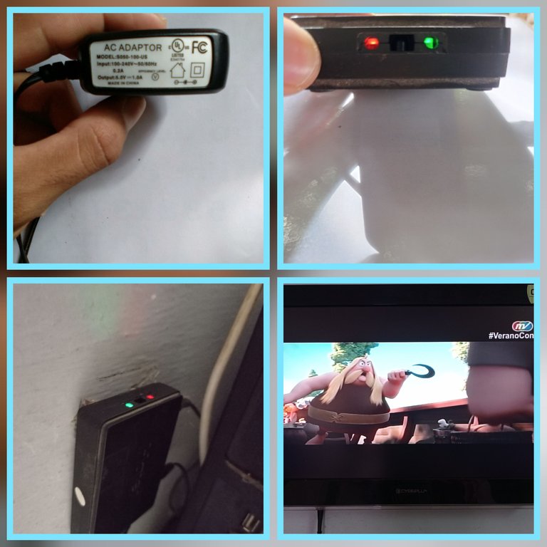
In this case it is the other model of DTT decoder (HDMB-2000 t/m) that is simpler than the previous one, but that when connecting it did not make absolutely nothing,
and its power supply is provided by an independent source that I will show you in the following image.
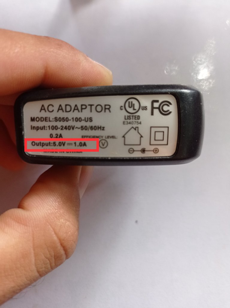
AC adapter with an output of 5 volts direct and 1 amp of current. Since the decoder did not react when the adapter was connected, the first thing I did was to measure the output of the adapter with a multimeter.
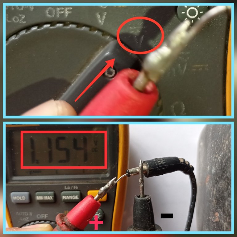
With the multimeter on the direct voltage scale (indicated in the first image of the collage), I measured the output of the adapter, yielding a reading of 1.154 volt (second image of the collage), however 5 volts should be present as indicated by the adapter characteristics, so this adapter is faulty.
REPAIRING THE ADAPTER...
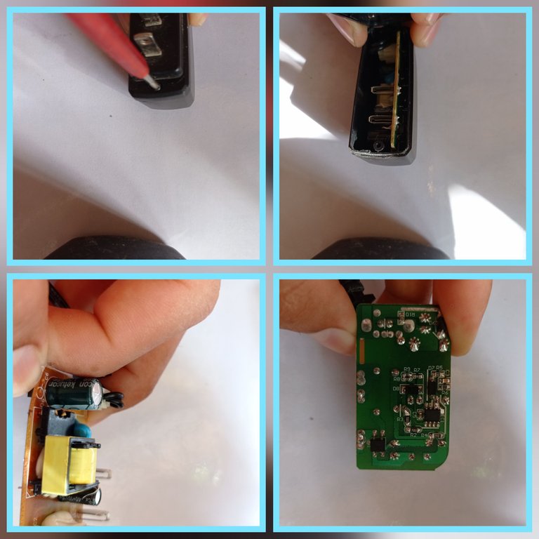
I disassembled the adapter by removing the only screw it has, and then performed a visual inspection of the board and components.
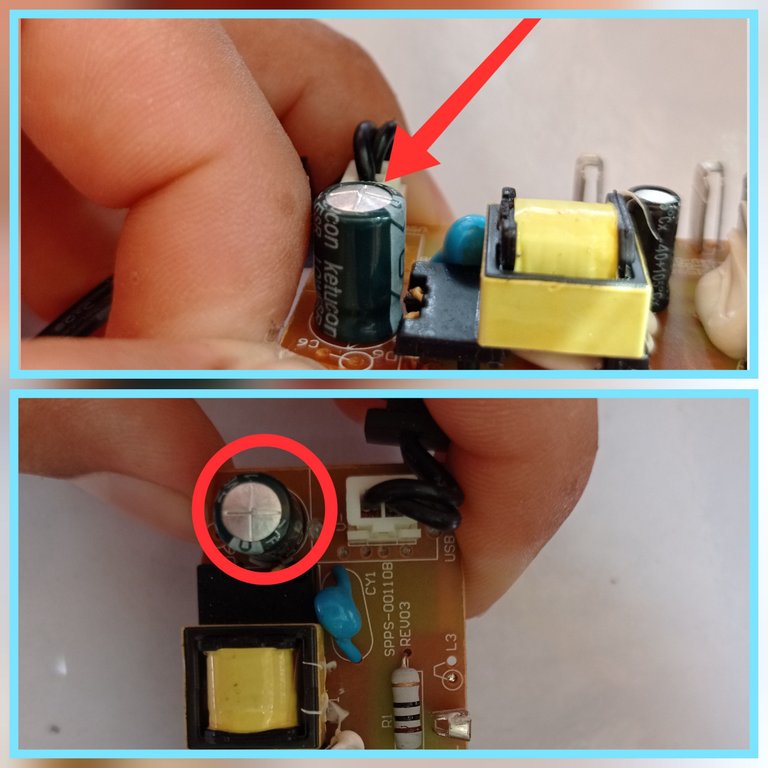
As a result of the visual inspection I was able to determine that the electrolytic capacitor of 470 uF(micro Farads)/10 volt that is connected to the 5 volt output, was swollen as shown in the collage images. This caused the adapter to present too many variations in the output voltage, and is the reason why the reading on the multimeter on the direct scale was 1.154 volt, in addition to not guaranteeing the operation of the decoder.
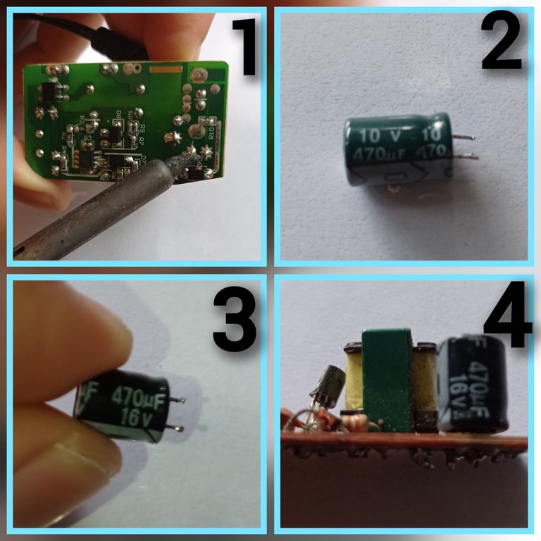
1-The first step was to remove the electrolytic capacitor with the help of a soldering iron.
2-Physically deformed capacitor, which lost the electrical properties for which it was designed.
3-Electrolytic capacitor in good condition, which I extracted from another electronic board, this was the one I used to replace the one that was in poor condition, if you look at the characteristics, it has the same capacity (470 uF), however supports 16 volt. I clarify that when replacing an electrolytic capacitor must be replaced by one of equal or superior characteristics, but never by one that presents electrical characteristics lower than those of the one to be replaced.
4- As fourth step, I soldered in the plate of the adapter the capacitor in good condition, being as it is shown in the fourth image of the collage.
Performing the measurements...
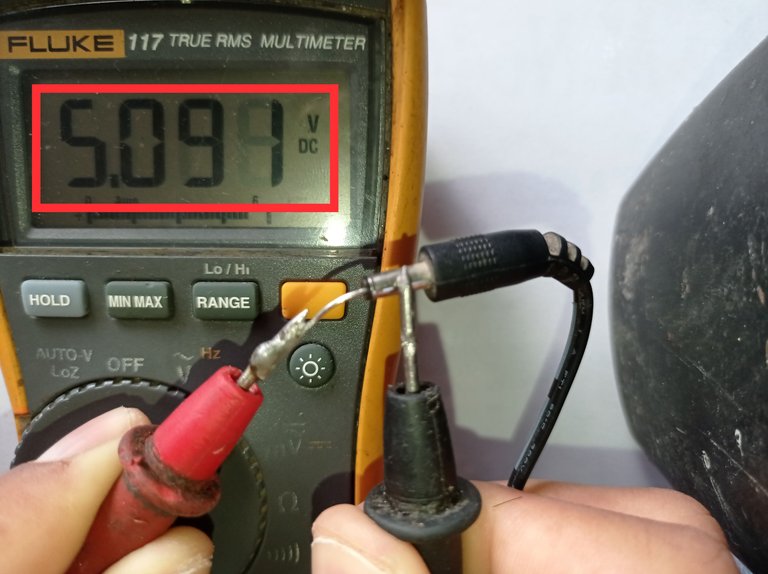
After replacing the bad electrolytic capacitor, I measured the output again, and this time the measurement was correct (5 volts), so the adapter was repaired.*
Final Results
I reversible the adapter, powered the decoder to test it and it worked correctly, then I placed the decoder in its usual position and connected it to the TV.
In this way I gave solution to the two failures, one was easier than the other, but luckily I was able to solve both problems, and everyone at home was happy and enjoying the TV programming.
I hope my experience during this situation has helped you, if you got this far reading my post I thank you, leave in the comments if you consider it convenient, any suggestions, questions or just a greeting, I will be grateful for that.
Greetings and see you next post 😉.
The images were taken with my Xiaomi Redmi Note 6 Pro cell phone.
Images edited in the "Gallery" application of the phone and the application Photo Collage-GridArt.
The background of the cover collage image was generated with Bing AI.
Text translated to English in Deepl translator.
You can see me on Facebook
ESPAÑOL
Saludos a toda la comunidad, una vez más es un placer estar por acá compartiendo mis experiencias con ustedes. Les comento que recientemente se me dió una de esas situaciones en casa en las que se averian varios equipos prácticamente al mismo tiempo, o con un intervalo de tiempo muy corto y te ponen a correr. El caso es que tengo dos televisores, uno en la sala que es usado mayormente por mi abuelo y otro en mi cuarto, que es el que uso yo. Cada TV, está conectado con su decodificador de Televisión Digital Terrestre (TDT), sin embargo los dos decodificadores se averiaron quedándonos prácticamente sin poder ver la televisión, pues aunque todavía existe la posibilidad de ver la televisión analógica, lo cierto es que solo existen cuatro o cinco canales analógicos según la región del país, por lo que quedamos limitados a solo ver esos canales.
Así que me di a la tarea de reparar lo más rápido posible los dos Decodificadores TDT, y en lo adelante les contaré cuáles fueron las fallas y como las resolví.
Primeramente les mostraré los dos Decodificadores TDT.
1- Mico_DTMB_DT46
2- Haier HDMB-2000t/m
Análisis de la falla y reparación del decodificador TDT conectado en el TV de la Sala (1).
El síntoma de este decodificador es que no mostraba vídeo por la salida RCA que se conecta al TV, además de que no encendían ninguno de los LED indicadores ni el panel siete segmentos que muestran el estado de encendido o apagado del decodificador, sin embargo al conectarlo a la toma de corriente alterna había un cambio de coloración en el TV que me demostraba que el decodificador intentaba encender pero en todo momento permanecía la pantalla en negro, o sea el cambio de coloración en la pantalla era de un negro intenso a uno más claro, pero en ningún momento mostraba imagen alguna.
DESARMANDO EL DECODIFICADOR.
Este decodificador en particular se desarma retirando los tornillos que señalo en la imagen con las flechas.
Luego de retirar la tapa se pueden observar tres bloques principales dentro del decodificador
1- Fuente conmutada que provee los 5 volt de corriente directa con los que se alimenta la placa principal.
2- Placa principal donde de forma general se lleva a cabo el procesamiento de las señales TDT
3- Panel frontal donde están presentes los diferentes LED indicadores, por ejemplo: Indicador de encendido y apagado, panel siete segmentos y LED infrarrojo que recibe las señales del mando a distancia
LO PRIMERO QUE DEBEMOS HACER AL REPARAR CUALQUIER EQUIPO.
Cuando reparamos un equipo el primer paso es realizar una buena inspección visual del mismo, en ocasiones las fallas se manifiestan físicamente en las superficies de los componentes o placas electrónicas, ejemplo: deformación del componente, cambios de coloración, soldaduras frías, conexiones quebradas, golpes etc. Al detectar cualquiera de estos rasgos físicos en la placa se nos pude facilitar grandemente la reparación.
A simple vista al chequear las placas del decodificador no se observaron alteraciones físicas como las descritas anteriormente. Sin embargo mirando detenidamente y tomando como experiencia otras reparaciones en las que la falla ha estado originada por la acción corrosiva de cierto pegamento que utilizan algunos fabricantes en las placas electrónicas para fijar algunos componentes, me detuve en la placa del panel frontal, la cual tenía este pegamento que supuestamente le daba firmeza a un condensador, al retirar el pegamento mis sospechas fueron confirmadas como les muestro en las siguientes imágenes.
Está imagen fue tomada en otro decodificador por el usuario @Tloarreglo del grupo CACHARREROS de Cuba en la red social Telegram, al cual le pedí autorización para mostrar su foto en este post, con el objetivo de mostrar el pegamento al que me referí anteriormente, debido a que no tomé fotos en mi decodificador antes de retirar dicho pegamento
Aquí se observa como al retirar el pegamento y raspar bien las calles detecté que estaban interrumpidas producto a la corrosión del pegamento
Nota: Este pegamento al parecer tiene componentes químicos que tinen una acción corrosiva en el cobre de las conexiones de la placa, sin embargo los fabricantes lo siguen empleando. Mi opinión es que lo hacen intencionalmente pues dudo mucho que no tengan conocimientos del daño que le ocasiona a las placas, es lento pero seguro. Siempre que lo veo me llega a la mente un tema en la electrónica actual:Obsolencia Programada, y aunque no estoy seguro de que el empleo de esta sustancia forme parte de este tema de la Obsolencia, lo cierto es que es una bomba de tiempo que es perfectamente conveniente para los fabricantes.
Mi consejo: siempre que lo vean, retiren todo el pegamento y limpien bien el área con algún limpiador electrónico, o alcohol, si es isopropílico mucho mejor.
Aunque a simple vista se ven tres calles interrumpidas, es mejor comprobar que exista continuidad entre cada punto señalado dentro del óvalo azul con su correspondiente punto de conexión, como se señala con las flechas, para esto usé el multímetro en escala de continuidad( señalado en la primera imagen del collage), punta negra del multímetro en los puntos de conexión señalados dentro del óvalo y punta roja al final de cada calle, se comprueba punto por punto que exista continuidad.
En mi caso solo habían tres calles en mal estado y fueron las que se pueden observar a simple vista
1-Con ayuda de un cúter raspé cuidadosamente las calles en mal estado.
2- Apliqué alcohol al 96 % para limpiar bien el área con un cepillo de dientes y eliminar los restos del pegamento que dañó las calles.
3- Regulé mi cautín a 350°C
4- Apliqué estaño a las calles para posteriormente puentear con alambres finos como les muestro en la siguiente imagen
Calles puenteadas con alambres finos
Luego de puentear las calles y probar el funcionamiento del decodificador pensando que se resolvería el problema, me di cuenta de que todavía había otra avería pues no encendía el panel frontal, por lo que continúe buscando y pude descubrir que al conectar el panel frontal, el voltaje de 5 volts proveniente de la fuente conmutada se caía a 0.8 volt. Esto quiere decir que había un sobre consumo producido por un cortocircuito.
Con el multímetro en escala de continuidad y la placa desconectada de la fuente , medi entre el terminal por el que ingresan los 5 volt y el terminal de tierra (GND) arrojando una lectura de continuidad que evidencia un cortocircuito entre los 5 volts y tierra, por lo que tuve que chequear todos los componentes asociados a la línea de 5 volt
Después de hacer varias mediciones e ir descartando los componentes en buen estado, logré dar con el culpable, el cual era el condensador smd que les muestro en la foto, estaba en corto internamente,esto suele suceder con estos condensadores smd, los mismos tienden a ponerse en cortocircuito, inhabilitando un equipo por completo
Sustitui el condensador smd en corto por uno similar y en buen estado, además volví a soldar el condensador electrolítico ( señalado en un círculo rojo) que tuve que retirar al inicio para trabajar con más comodidad en la placa.
LISTO!! ES HORA DE PROBAR NUEVAMENTE LA PLACA...
Conecté nuevamente la ficha de conexión del panel frontal, alimenté el decodificador y este fue el resultado, trabajando ok para mi grata sorpresa.
Luego armé nuevamente el decodificador TDT exactamente como estaba antes de desarmarlo, lo conecté a la TV, y estos fueron los resultados finales.
Un equipo reparado, ahora falta el otro...
En este caso se trata del otro modelo de decodificador TDT(HDMB-2000 t/m) que es más sencillo que el anterior, pero que al conectarlo no hacia absolutamente nada,
y su alimentación la provee una fuente independiente que le mostraré en la siguiente imagen
Adaptador de corriente alterna con una salida de 5 volts de directa y 1 amper de corriente. Debido a que el decodificador no reaccionaba al conectarle el adaptador, lo primero que hice fue medir con un multímetro la salida del mismo.
Con el multímetro en la escala de voltaje de directa (señalado en la primera imagen del collage), medí la salida del adaptador, arrojando una lectura de 1.154 volt (segunda imagen del collage), sin embargo deberían estar presente los 5 volt como indican las características del adaptador, por lo que este adaptador está averiado
REPARANDO EL ADAPTADOR...
Desarmé el adaptador retirando el único tornillo que posee, y luego le realicé una inspección visual a la placa y a los componentes
Cómo resultado de la inspección visual pude determinar que el condensador electrolítico de 470 uF(micro Faradios)/10 volt que está conectado a la salida de los 5 volts, se encontraba hinchado como se señala en las imágenes del collage. Esto provocaba que el adaptador presentara demasiadas variaciones en el voltaje de salida, y es el motivo por el que la lectura en el multímetro en la escala de directa fuera de 1.154 volt , además de no garantizar el funcionamiento del decodificador
1-El primer paso fue retirar el condensador electrolítico con ayuda del soldador cautín
2- Condensador deformado físicamente, el cual perdió las propiedades eléctricas para el cual fue diseñado
3-Condensador electrolítico en buen estado, el cual extraje de otra placa electrónica, este fue el que utilicé para sustituir el que estaba en malas condiciones, si se fijan en las características, presenta la misma capacidad (470 uF), sin embargo soporta 16 volt. Aclaro que al sustituir un condensador electrolítico se debe sustituir por uno de características iguales o superiores, pero nunca por uno que presente características eléctricas menores a las del que se quiere sustituir.
4- Cómo cuarto paso, soldé en la placa del adaptador el condensador en buen estado, quedando como se muestra en la cuarta imagen del collage
Realizando las mediciones...
Luego de sustituir el condensador electrolítico en mal estado, volví a medir la salida, y está vez la medición arrojó un resultado correcto(5 volts), por lo que el adaptador fue reparado
Resultados Finales
Armé nuevamente el adaptador, alimenté el decodificador para probarlo y funcionó correctamente, luego coloqué el decodificador en su posición habitual y lo conecté al TV
De esta forma le di solución a las dos averías, una fue más sencilla que otra, pero por suerte pude resolver los dos problemas, y todos en casa quedamos felices y disfrutando de la programación televisiva.
Espero les haya servido de algo mi experiencia durante está situación, si llegaste hasta aquí leyendo mi post te lo agradezco, deja en los comentarios si lo estimas conveniente, cualquier sugerencia, duda o simplemente un saludo, yo me sentiré agradecido por eso.
Un saludo y hasta el próximo post 😉
Las imágenes fueron tomadas con mi celular Xiaomi Redmi Note 6 Pro.
Imágenes editadas en la aplicación "Galería" del teléfono y la aplicación Foto Collage-Grid
El fondo del collage de la portada fue generado con la IA de Bing.
Puedes verme en Facebook
Interesante ese producto conozco la marca haier pero nunca lo había visto me gustó mucho tu post.
Gracias por comentar, es un placer, saludos amigo.
Congratulations @darknapol! You have completed the following achievement on the Hive blockchain And have been rewarded with New badge(s)
Your next target is to reach 800 upvotes.
You can view your badges on your board and compare yourself to others in the Ranking
If you no longer want to receive notifications, reply to this comment with the word
STOPCheck out our last posts:
Saludos amigo @darknapol muy gráfica tu explicación y excelente reparación, gracias por compartir.
Gracias a ti por comentar. Saludos amigo
Congratulations @darknapol! You received a personal badge!
You can view your badges on your board and compare yourself to others in the Ranking
Check out our last posts: